Use this method if you install a 5050s in IC14 and you get a MIL code 21.
STEP 1 modify and install the VTEC parts as normal but stop at the installation of IC14
STEP 2 install the 5050s in the IC14 position and do not solder pin 4 of the 5050s
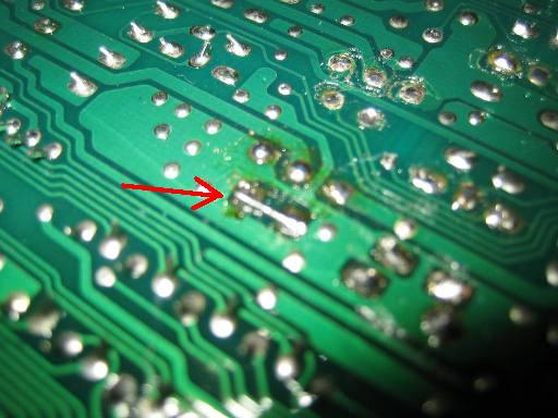
 STEP 3 on the PCB of the ECU bridge pads 2 and 4 ( do not bridge the legs of the 5050s )
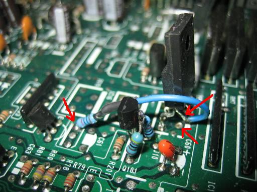
 STEP 4 get a 820R resistor and solder 4cm of wire to one side and solder the other end of the resistor to the emitter of Q102 ( as a 5v ref )
STEP 5 solder the other side of the wire to pin 4 of the 5050s, you might want to trim back the leg a bit so it doesnt stick out to much.
STEP 4 get a 820R resistor and solder 4cm of wire to one side and solder the other end of the resistor to the emitter of Q102 ( as a 5v ref )
STEP 5 solder the other side of the wire to pin 4 of the 5050s, you might want to trim back the leg a bit so it doesnt stick out to much.
 and thats it, enjoy your VTEC
I tested a ECU with this method on the Engine Simulator in VTEC for over 5 minuits continuously and it did not mis a beat and nothing got to hot.
link to thread http://forum.pgmfi.org/viewtopic.php?t=12672
cheers
John
b16A2
and thats it, enjoy your VTEC
I tested a ECU with this method on the Engine Simulator in VTEC for over 5 minuits continuously and it did not mis a beat and nothing got to hot.
link to thread http://forum.pgmfi.org/viewtopic.php?t=12672
cheers
John
b16A2
|
Copyright © 2002-present by the contributing authors. All material on this collaboration platform is the property of the
contributing authors, and is covered by the Non-Commercial Share-Alike License unless explicitly stated otherwise. |
|