 |
 |
You will need bridge J1 on the back of the ECU.
 Add C49 & C50 and C92 on back. C91 is on the front by the latch
C49 & C50 --> .004UF (Digikey part number 399-1230-1-nd )
C91 & C92 --> .00001UF ( digikey Part Number 399-1192-1-nd )
Add C49 & C50 and C92 on back. C91 is on the front by the latch
C49 & C50 --> .004UF (Digikey part number 399-1230-1-nd )
C91 & C92 --> .00001UF ( digikey Part Number 399-1192-1-nd )
 Add the 74hc373 SMD chip. (MFG part# SN74HC373NSR, Digi-Key Part Number 296-8310-1-ND)
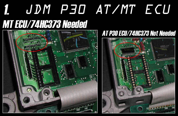 The Above picture is untrue, many A/T boards need the latch and the socket. As there are different variants of the JDM P30 Board
Add a 29C256 eprom with bin written to it.
For RTP/Datalogging w/ Crome remove J4 on front. (J4 is a 000 resistor)
Solder in a 4 pin header (snappable header pins 1x40 work GREAT for this and are VERY cheap)
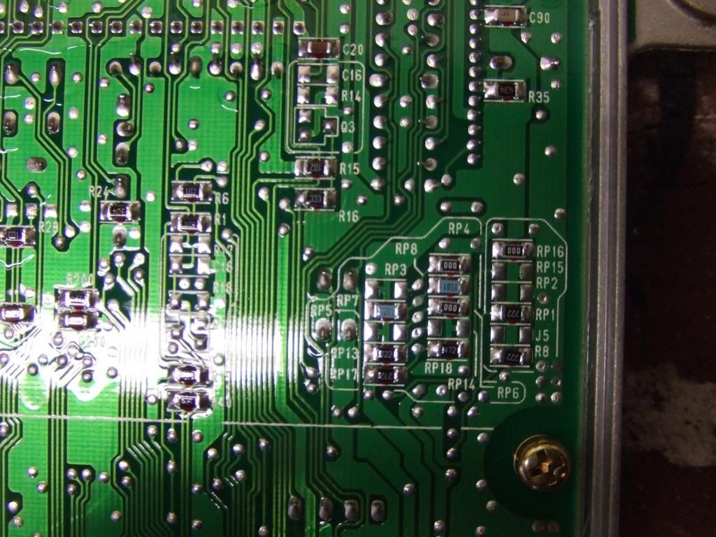
Lastly if you are wanting to convert Auto to manual remove the resistor RP18 '472' on the back and replace it with a jumper wire. Also remove RP17 and leave it open. A/T resistor layout shown in bottom right of the picture.
The Above picture is untrue, many A/T boards need the latch and the socket. As there are different variants of the JDM P30 Board
Add a 29C256 eprom with bin written to it.
For RTP/Datalogging w/ Crome remove J4 on front. (J4 is a 000 resistor)
Solder in a 4 pin header (snappable header pins 1x40 work GREAT for this and are VERY cheap)
Lastly if you are wanting to convert Auto to manual remove the resistor RP18 '472' on the back and replace it with a jumper wire. Also remove RP17 and leave it open. A/T resistor layout shown in bottom right of the picture.
 All info is from the following threads:
http://forum.pgmfi.org/viewtopic.php?t=3112&highlight=chipping+jdm+computers
Special thanks to all the contributors of the above thread and katman for doing the pics in
the first place... We love you katman :)
http://forum.pgmfi.org/viewtopic.php?t=4005&highlight=chipping+jdm+computers
Thanks to infotechplus for pics and info on C49,C50,C91,C92
All info is from the following threads:
http://forum.pgmfi.org/viewtopic.php?t=3112&highlight=chipping+jdm+computers
Special thanks to all the contributors of the above thread and katman for doing the pics in
the first place... We love you katman :)
http://forum.pgmfi.org/viewtopic.php?t=4005&highlight=chipping+jdm+computers
Thanks to infotechplus for pics and info on C49,C50,C91,C92
|
Copyright © 2002-present by the contributing authors. All material on this collaboration platform is the property of the
contributing authors, and is covered by the Non-Commercial Share-Alike License unless explicitly stated otherwise. |
|