 |
 |
Thanks to ltdannear for lots of help in getting this to work.
The following is a guideline for how to debug the datalogging circuit you have added to your ECU. This guidline is based on the USBMOD3 datalogging circuit I integrated into my JDM P30-901 ECU (converted to manual).
Before you start, use an ohmmeter to ensure you have good solder joints and connectors on the TTL-level asynchronous serial port of the ECU. Ensure there are no solder bridges between any of the CN2 pads. Ensure CN2 Pin 1 has connectivity to ground. Ensure CN2 Pin 2 has connectivity to the 66207 processor Pin 42 (surface mount) or Pin 39 (DIP), Rx Data. Ensure CN2 Pin 3 has connectivity to any Vcc pin of any IC, I used Pin 28 of the PROM socket. Ensure CN2 Pin 4 has connectivity to IC19 Pin 6 (surface mount), this must be Tx Data. As of 1/2/05, this is backwards from Nicolas Mailloux's document on http://www.ecucontrol.com/seria_ladapter.htm. I will ping him to resolve this.
For my ROM Editor, I used CROME Beta 1.1.0 w/ BoostTools+, downloaded from the Sticky: RELEASE: CROME Beta 1.1.0 w/ BoostTools+ topic in the CROME Forum, post dated: Sun Dec 26, 2004 5:51 am. http://forum.pgmfi.org/viewtopic.php?p=30368#30368
After you have installed CROME, go to the Sticky: Quick Datalogger topic in the CROME Forum. Download and unzip John Cui's second quickDLRTP.js plugin file (post is dated: Mon Nov 22, 2004 1:24 pm, not the one in the first post). http://forum.pgmfi.org/viewtopic.php?p=28536#28536 Go into Crome plugin manager, select the built-in quickDLRTP.js entry, and click on delete to get rid of it. Click on "Install New Plugin" and point to the directory you put quickDLRTP.js into, and finish adding it into Crome. This replaces the DT5 code that gets put into the PROM by CROME Beta 1.1.o w/ BoostTools+.
Start CROME. Open the .bin you want to use (I used a stock P30-203). Under Plugins, Enhancements, select "Remove Checksum Routine" to remove the checksum. Under Plugin, Enhancements, select "Quick Datalogger +RTP" to add in the DT5 datalogger code. Since I am running a JDM P30, I need to select the options tab, uncheck the Disable Knock Sensor box, and check the Disable ELD, Disable PA Sensor and Disable Injector Test boxes. Save the binary into a new .bin file. The DT5 datalogging code automatically sets the ECU communications to 38,400 baud, 8 bits, 1 stop bit, no parity, no flow control.
Burn the .bin into a PROM, and put it in the ECU. BTW, just to be safe, make sure you power down the ECU before swapping proms. If its on the bench, turn off the power supply. If it is in the car, pull the two ECU fuses, just to be safe.
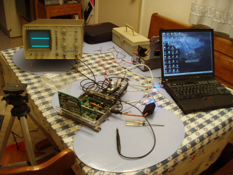
The ECU only needs to be powered up to test the link. I tested mine on the bench, with just the power and ground pins hooked up, an LED and resistor on the CEL signal and a switch on the Service Check Connector circuit. Heres a picture of my bench setup,
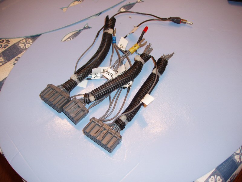
 and heres one of my bench harness.
 Of course, on this bench, the data coming from the ECU is garbage, because nothing is hooked up. I also see a solid CEL with this setup (no solid CEL in the car), but the datalogging still will work. You can do the same thing in the car by turning the ignition on without starting the engine, but the data will report whatever the sensors are reading without the engine running. If the engine is running, you'll get changing data.
Make sure your USBMOD3 driver is set to 38,400 baud, 8 bits per character, 1 stop bit, no parity, no flow control. You set this via Device Manager under system in the Control Panel.
I really like ltdannear's new open source datalogger. I am using version 20 from the OBD1 Forum, in the "We need some open source datalogging." topic. It is from the 9th page, and the post is dated: Sat Dec 18, 2004 4:19 pm. http://forum.pgmfi.org/viewtopic.php?p=30016#30016
After youve started the datalogger, select the communications tab to set the com port and parameters. Select the Data Capture tab and click on the Data Capture button. The Data Capture window will start to fill with data after you select the Live Data Tab, and click on "Start". At that point, the datalogger starts sending commands to the ECU and the ECU sends data back. I hooked the lower trace of my scope to the Rx Data signal of the ECU (CN2 Pin 4) and the upper trace of my scope to the Tx Data signal if the ECU (CN2 Pin 2). I triggered off the lower trace, negative slope. Here is the first picture I took of the scope,
Of course, on this bench, the data coming from the ECU is garbage, because nothing is hooked up. I also see a solid CEL with this setup (no solid CEL in the car), but the datalogging still will work. You can do the same thing in the car by turning the ignition on without starting the engine, but the data will report whatever the sensors are reading without the engine running. If the engine is running, you'll get changing data.
Make sure your USBMOD3 driver is set to 38,400 baud, 8 bits per character, 1 stop bit, no parity, no flow control. You set this via Device Manager under system in the Control Panel.
I really like ltdannear's new open source datalogger. I am using version 20 from the OBD1 Forum, in the "We need some open source datalogging." topic. It is from the 9th page, and the post is dated: Sat Dec 18, 2004 4:19 pm. http://forum.pgmfi.org/viewtopic.php?p=30016#30016
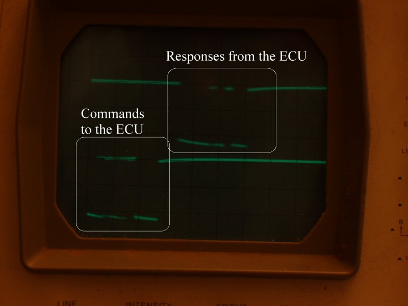
After youve started the datalogger, select the communications tab to set the com port and parameters. Select the Data Capture tab and click on the Data Capture button. The Data Capture window will start to fill with data after you select the Live Data Tab, and click on "Start". At that point, the datalogger starts sending commands to the ECU and the ECU sends data back. I hooked the lower trace of my scope to the Rx Data signal of the ECU (CN2 Pin 4) and the upper trace of my scope to the Tx Data signal if the ECU (CN2 Pin 2). I triggered off the lower trace, negative slope. Here is the first picture I took of the scope,
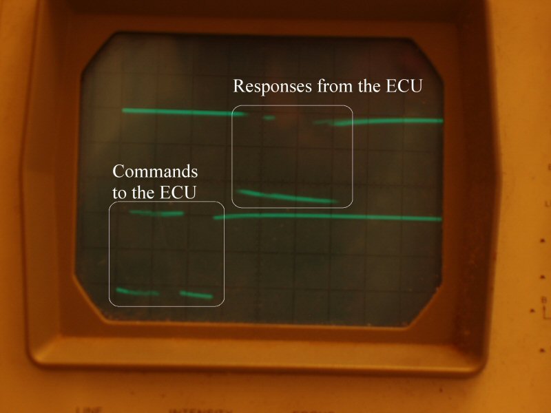
 and here is the second.
 While you are looking at live data coming from the ECU, you can go to the "Gauges" menu item and select the "Display gauges 800x600" item. I haven't tested the 640x480 display. With the live data started, you can select "Activate Gauges" and the gauges will work. BTW, I triple, triple checked the Tx Data and Rx Data wiring to ensure I got the crossover right between the ECU and the USBMOD3. If you are not able to see datalogging after you have started it, the first thing to do is swap the Tx Data and Rx Data pins in the connector.
To log data using lts datalogger, select the file name and folder you want it to save your datalog to and click save. Start datalogging. Every few minutes (400 samples of data) it will append that data to the file. If you check the auto-save option. just start datalogging afterwards. It will dump to the C:\ directory (or to whatever directory you specify in the Communications tab). File will be named 01-01-05.csv (or whatever the current date is.)
If you use John Cuis old Cuddle datalogger (Cuddle Forum, Topic: "ATTN: John Cui your site is down (temporary download here)", post dated: Fri Oct 03, 2003 3:22 pm) http://forum.pgmfi.org/viewtopic.php?p=20462#20462, make sure you select the correct port and set the baud rate to 43,800 baud. Once the gauges come up on the PC screen, nothing happens until you click on the red button below the A/F gauge and the Speedometer. At that point, the button turns green and Cuddle starts sending DT5 commands to the ECU, and the ECU starts ending data back, and the gauges move if the car is running. You can click on the "Start Datalogging" button to start logging the data for saving to a file.
The new Cuddle gauges, Duddle.beta.0.0.1 (The first Cuddle download in the Cuddle Forum, RELEASE topic, Dated: Mon Oct 25, 2004 9:02 pm) works ok. http://forum.pgmfi.org/viewtopic.php?p=27027#27027 You need to set the communications port and parameters in the associated .ini file before you start it. Just click on the start/stop button and it starts sending DT5 commands to the ECU, and the ECU starts ending data back, and the gauges move if the car is running.
I was getting weird results from Uberdata 1.7, http://www.ecimulti.org/uberdata/ until I figured out that I need to open their P30 import only .bin. Then I click on the Datalogging tab. Check the sensors you want to log, then go to the "Select O2" dropdown box to select your O2 sensor. I needed to select the stock O2 sensor. Finally, after you have everything else is set up, go to the "Select Port" dropdown box to select the proper port. Selecting the port starts Uberdata sending commands to the ECU, and the ECU starts sending data back. There are no gauges I can find.
I hope this helps you to debug your datalogging setup. Feel free to add your input.
-- markolson - 01 Jan 2005
While you are looking at live data coming from the ECU, you can go to the "Gauges" menu item and select the "Display gauges 800x600" item. I haven't tested the 640x480 display. With the live data started, you can select "Activate Gauges" and the gauges will work. BTW, I triple, triple checked the Tx Data and Rx Data wiring to ensure I got the crossover right between the ECU and the USBMOD3. If you are not able to see datalogging after you have started it, the first thing to do is swap the Tx Data and Rx Data pins in the connector.
To log data using lts datalogger, select the file name and folder you want it to save your datalog to and click save. Start datalogging. Every few minutes (400 samples of data) it will append that data to the file. If you check the auto-save option. just start datalogging afterwards. It will dump to the C:\ directory (or to whatever directory you specify in the Communications tab). File will be named 01-01-05.csv (or whatever the current date is.)
If you use John Cuis old Cuddle datalogger (Cuddle Forum, Topic: "ATTN: John Cui your site is down (temporary download here)", post dated: Fri Oct 03, 2003 3:22 pm) http://forum.pgmfi.org/viewtopic.php?p=20462#20462, make sure you select the correct port and set the baud rate to 43,800 baud. Once the gauges come up on the PC screen, nothing happens until you click on the red button below the A/F gauge and the Speedometer. At that point, the button turns green and Cuddle starts sending DT5 commands to the ECU, and the ECU starts ending data back, and the gauges move if the car is running. You can click on the "Start Datalogging" button to start logging the data for saving to a file.
The new Cuddle gauges, Duddle.beta.0.0.1 (The first Cuddle download in the Cuddle Forum, RELEASE topic, Dated: Mon Oct 25, 2004 9:02 pm) works ok. http://forum.pgmfi.org/viewtopic.php?p=27027#27027 You need to set the communications port and parameters in the associated .ini file before you start it. Just click on the start/stop button and it starts sending DT5 commands to the ECU, and the ECU starts ending data back, and the gauges move if the car is running.
I was getting weird results from Uberdata 1.7, http://www.ecimulti.org/uberdata/ until I figured out that I need to open their P30 import only .bin. Then I click on the Datalogging tab. Check the sensors you want to log, then go to the "Select O2" dropdown box to select your O2 sensor. I needed to select the stock O2 sensor. Finally, after you have everything else is set up, go to the "Select Port" dropdown box to select the proper port. Selecting the port starts Uberdata sending commands to the ECU, and the ECU starts sending data back. There are no gauges I can find.
I hope this helps you to debug your datalogging setup. Feel free to add your input.
-- markolson - 01 Jan 2005
| Attachment?: | Modify: | Size: | Date: | Who: | Comment: |
|---|
 BenchHarnessA.JPG BenchHarnessA.JPG | mod | 132604 | 01 Jan 2005 - 08:18 | markolson | Bench test harness: Power, Ground, CEL, SCS Switch |
| BenchSetUpA.JPG | mod | 157732 | 01 Jan 2005 - 08:21 | markolson | Bench Setup: Test Harness, Power Supply, PC, Scope |
| Datalogging1A.JPG | mod | 101087 | 01 Jan 2005 - 08:27 | markolson | Scope shot of working datalogging signals |
| Datalogging2A.JPG | mod | 103893 | 01 Jan 2005 - 08:30 | markolson | Scope shot with longer exposure |
|
Copyright © 2002-present by the contributing authors. All material on this collaboration platform is the property of the
contributing authors, and is covered by the Non-Commercial Share-Alike License unless explicitly stated otherwise. |
|