 |
 |
Using the Unused Analog Input D12 on OBD1 ECUs to Log Analog Input Such as Exhaust Gas Temperature.
All of the testing was done on a USDM P30 OBD1 ECU and all of the modifications and testing was done on a JDM P30 OBD1 ECU, but other Honda OBD1 ECUs should be the same.
There are differences between the circuits connected to the USDM P30 and the JDM P30:
USDM P30:
-All of the components are installed in the USDM P30.
-The USDM P30 D12 circuit is simpler that the one in the JDM P30.
-AI5 in the USDM P30 (66207 Pin59 of the 64 pinDIP package) is grounded.
-The USDM D12 circuitry leads to AI3 (66207 Pin57 of the 64 pinDIP package) in the USDM P30 which is logged in the following way:
*066h = the two most significant bits are the two least significant bits of the 10 bit value saved by the A/D converter for AI3 analog input.
*067h = the most significant 8 bits of the 10 bit value saved by the A/D converter for AI3 analog input.
JDM P30:
Not all components are installed in the JDM P30.
The JDM P30 D12 circuit is more complex than the one in the USDM P30.
AI3 in the USDM P30 (66207 Pin 61 of the 68 pin PLCC package) is grounded.
The USDM D12 circuitry leads to AI5 (66207 Pin 63 of the 68 pin PLCC package) in the JDM P30 which is logged in the following way:
*06Ah = the two most significant bits are the two least significant bits of the 10 bit value saved by the A/D converter for AI5 analog input.
*06Bh = the most significant 8 bits of the 10 bit value saved by the A/D converter for AI5 analog input.
The USDM P30 D12 input can be used to log 0-5V analog input such as from an Exhaust Gas Temperature thermocouple amplifier. I tested the D12 input on my USDM P30 by using a 10K ohm pot used as a variable voltage divider across a 5V power supply. I also tested it with my EGADS EGT sensor, and it works very well as an EGT logging input.
The JDM P30 ECU must be modified in order to use D12 to log 0-5V analog input such as from an Exhaust Gas Temperature thermocouple amplifier.
CAUTION:
While the JDM D12 mod works well electronically, there appears to be OBD1 code that reads the AI5 analog input and performs some sort of function. Until this code is understood, it is proabably safer to cut the traces on both the AI3 and AI5 analog inputs to the 66207. Then add a wire to ground AI5, and add a wire to run the D12 circuit to AI3. This pin swap will cause the JDM ECU to log exactly as the USDM ECU does. (Caution added -- markolson - 02 Jan 2006)
Here is a copy of the schematics for the D12 circuit in the
USDM P30 ECU.
- USDM P30 D12 schematics:

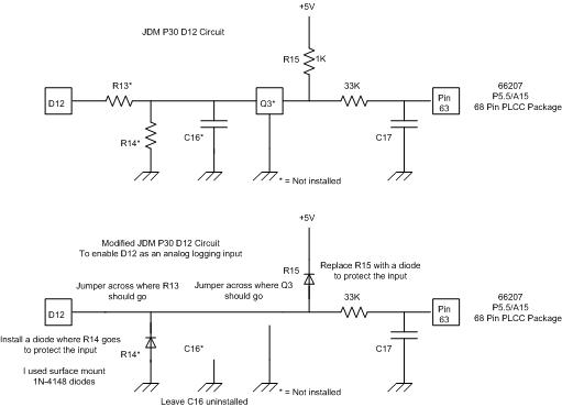
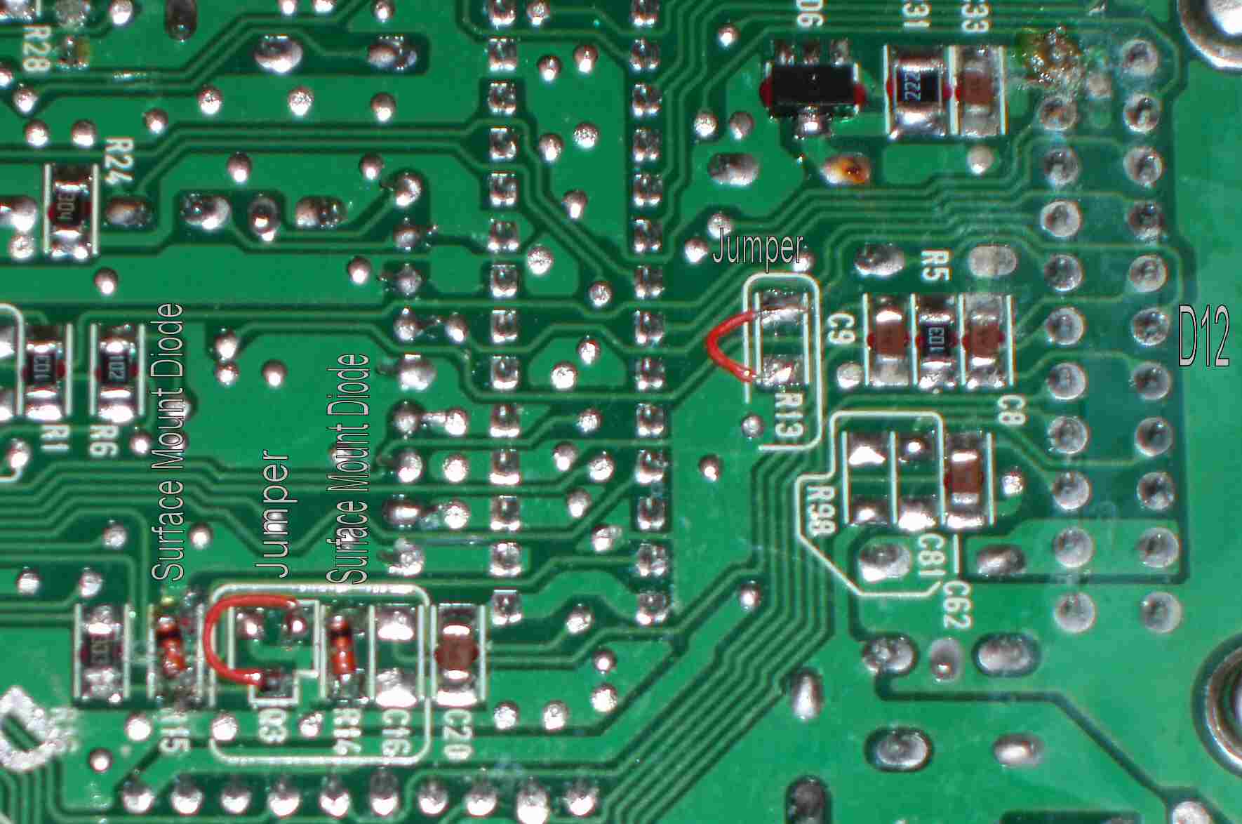
The JDM P30 D12 circuit can be modified in the following way to enable logging of analog inputs. All of these modifications are on the back of the ECU board. Replace R15 with a diode. Put another diode in the location marked for R14. These diodes protect the analog input of the 66207 chip. I used surface mount 1N-4148 diodes. Put a jumper across the location marked for R13 and across the non-ground connections of Q3 in order to get the signal from D12 to the modified circuit. Do not remove or change the 33K ohm R16 resistor or C17, whatever its value is. It looks like a tantalum cap. It is a very simple modification. I tested the D12 input on my JDM P30 by using a 10K ohm pot used as a variable voltage divider across a 5V power supply. I also tested it with my EGADS EGT sensor, and it works very well as an EGT logging input.
Here is a copy of the schematics of the JDM P30 D12 circuit before and after the modification.
- JDM P30 D12 mod schematics:

Here is a high resolution picture of the modified JDM P30 ECU enabling D12 as a 0-5V analog logging input.
- JDM P30 D12 mod to enable analog input logging:

Good luck.
-- markolson - 20 Nov 2005
|
Copyright © 2002-present by the contributing authors. All material on this collaboration platform is the property of the
contributing authors, and is covered by the Non-Commercial Share-Alike License unless explicitly stated otherwise. |
|