 |
 |
|
|
| Added: |
>
> |
%META:TOPICINFO{author="blundar" date="1080759600" format="1.0" version="1.1"}%
How to chip a ODB2 ECU
by Doc (edited by Dave)
Table of Contents:
Introduction
Contrary to popular belief, it is possible to chip a ODB2 ECU. It's not cheap like chipping an ODB0 or ODB1 ECU, but it works in a similar way. The ODB2 ECU's stores the program in the processor (such as the OKI 66507 used in OBD2 A ECUs) like the ODB1 ECU. Unlike OBD1, there is no place on the board for a eprom. In this case, we've to replace the processor with an reprogrammed one instead of replacing or adding an EPROM.
There is a programmable version of the 66507 available, called 66P507. Unfortunately, they are quite expensive and very hard to get. Additionally, they can only be programmed once! You can program this processor with a normal e-prom programmer and an adaptor socket for the processor. More about this later.
Inside an OBD2 ECU
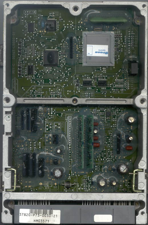
 You can see on the picture of the P73 the sqare processor (highlighted). The
processor is surface mounted, so you need experience in soldering surface mount
devices. One trick for beginners: a hot-air-gun (which you can get in your local hardware
store) works well and is a really effective SMT soldering tool for the price.
Chipping the ECU is straighforward: desolder the original processor, solder in a socket (PLCC84 for 66507), and finally put a preprogrammed replacement processor in to socket. There isn't really a lot more to say about this process, so let's take a look at the
programming adaptor.
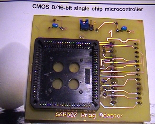
Programming a 66P507 using the adaptor
 Plug the adaptor on your e-prom programmer like a normal 27xxx eprom. Put a blank
66P507 in the empty (PLCC) socket on the top of the adaptor. Set your programmer
software to 27C512 and modify the target address to $0000-$BFFF. Use 12.5 Volt
programming voltage and a normal/slow programming alogorithm. Make sure the jumper
on the adaptor is set to the position "D". Now program the processor like it was an EPROM.
If you want to copy protect this processor so it cannot be read (easily - heh see Mcu Readers), you have to set the jumper to the position "S", and write to the address $0000 the value $00. DO THIS AFTER PROGRAMMING DATA, OTHERWISE THE PROCESSOR IS UNUSEABLE!
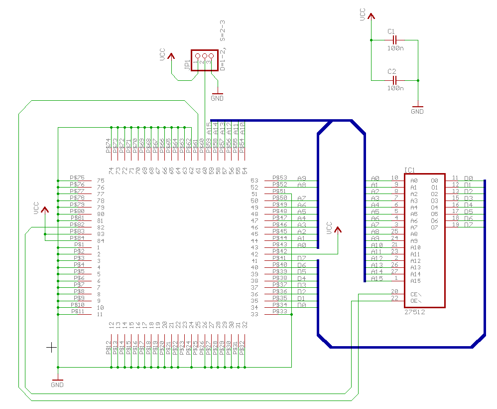
Schematic for programming adapter
If you want to build a programming adapter yourself: (click to enlarge)
 %META:FILEATTACHMENT{name="66p507prog_cheap.GIF" attr="h" comment="image schematic for a cheap 66P507 programmer" date="1080759145" path="C:\Documents and Settings\Administrator\Desktop\temp\wiki\obd2\66p507prog_cheap.GIF" size="23901" user="blundar" version="1.1"}%
%META:FILEATTACHMENT{name="spoon_p73_top.jpg" attr="h" comment="Chipped Spoon P73 ECU" date="1080759196" path="C:\Documents and Settings\Administrator\Desktop\temp\wiki\obd2\spoon_p73_top.jpg" size="88194" user="blundar" version="1.1"}%
%META:FILEATTACHMENT{name="66P507_progadaptorsized.jpg" attr="h" comment="Photo of adapter board" date="1080759224" path="C:\Documents and Settings\Administrator\Desktop\temp\wiki\obd2\66P507_progadaptor sized.jpg" size="90435" user="blundar" version="1.1"}%
 |
|
Copyright © 2002-present by the contributing authors. All material on this collaboration platform is the property of the
contributing authors, and is covered by the Non-Commercial Share-Alike License unless explicitly stated otherwise. |
|