 |
 |
|
<<O>> Difference Topic
Sim
(r1.3 - 28 Jan 2007 - Home.b16a2)
|
|
|
| Changed: |
<
< |
- I have added 4x 5w resistors to simulate the injectors.
| >
> |
- I have added 4x 12R 5w resistors to simulate the injectors.
|
| Changed: |
<
< |
- Im going to add an ELD from a fues box I have to simulate that. or at least to figure out what it does and when it does it, to help build a simulator for it.
| >
> |
- Iv added an ELD from a JDM ITR fuesbox, ran the main positive wire from the power supply through it to measure the current load. Even works with P13
|
| Changed: |
<
< |
On the side of the case, I cut out 3 holes to suit D25 computer connectors. simply A B and D, just like on the OBDI ecu, and to keep things simple everyting is wired the same as the OBDI standard which helps when probing with a multimeter for sensor signal. I than have made Harneses to suit OBDIIa, OBDIIb OBDO, and when I get some conectors OBDI ( rather than using a harness.)
| >
> |
On the side of the case, I cut out 3 holes to suit D25 computer connectors. simply A B and D, just like on the OBDI ecu, and to keep things simple everyting is wired the same as the OBDI standard which helps when probing with a multimeter for sensor signal. I then have made Harneses to suit OBDIIa, OBDIIb OBDO, and when I get some conectors OBDI ( rather than using a harness.)
|
| Added: |
>
> |
%META:FILEATTACHMENT{name="Engine_Sim019.jpg" attr="" comment="Close up of Distributor" date="1169987148" path="I:\Automotive\Misc\Engine Simulator\Pics\Engine_Sim 019.jpg" size="110159" user="b16a2" version="1.1"}%
%META:FILEATTACHMENT{name="Engine_Sim020.jpg" attr="" comment="Close up of O2 and VSS simulator" date="1169987200" path="I:\Automotive\Misc\Engine Simulator\Pics\Engine_Sim 020.jpg" size="104598" user="b16a2" version="1.1"}%
%META:FILEATTACHMENT{name="Engine_Sim022.jpg" attr="" comment="Close up of ELD" date="1169987284" path="I:\Automotive\Misc\Engine Simulator\Pics\Engine_Sim 022.jpg" size="88001" user="b16a2" version="1.1"}%
%META:FILEATTACHMENT{name="Engine_Sim023.jpg" attr="" comment="Close up back of control panel" date="1169987358" path="I:\Automotive\Misc\Engine Simulator\Pics\Engine_Sim 023.jpg" size="155808" user="b16a2" version="1.1"}%
%META:FILEATTACHMENT{name="Engine_Sim024.jpg" attr="" comment="Close up of main relay, knock, O2 heater" date="1169987428" path="I:\Automotive\Misc\Engine Simulator\Pics\Engine_Sim 024.jpg" size="106593" user="b16a2" version="1.1"}%
%META:FILEATTACHMENT{name="Engine_Sim025.jpg" attr="" comment="Close up of VTS and EACV" date="1169987506" path="I:\Automotive\Misc\Engine Simulator\Pics\Engine_Sim 025.jpg" size="74211" user="b16a2" version="1.1"}% |
|
<<O>> Difference Topic
Sim
(r1.2 - 28 Jan 2007 - Home.b16a2)
|
|
|
| Changed: |
<
< |
The pannel was drawn up in ms paint and printed on normal paper. Then used as a template on a peice of plastic from a sign and once the holes where all drilled then glued to the plastic with a clear coat of contact paper. then all the LEDs and Switched go in.
| >
> |
The pannel was drawn up in ms paint and printed on normal paper. Then used as a template on a peice of plastic from a sign and once the holes where all drilled then glued to the plastic with a clear coat of contact paper. then all the LEDs and switches go in.
|
| Changed: |
<
< |
there are so many uses for this thing from fault finding faults on an ECU at the component level to testing code and PGMFI parts.
| >
> |
There are so many uses for this thing from fault finding faults on an ECU at the component level to testing code and PGMFI parts. It is also interesting to see how and what ways you can upset the ECU by disconecting sensor ect whiel the engine sim is running.
|
| Changed: |
<
< |
Im working on an electronic distriblutor simulator. but for now I like the noise of something widing up. ( adds the fun to reving up the sim ) :)
| >
> |
Im working on an electronic distriblutor simulator, but for now I like the noise of something widing up. ( adds the fun to reving up the sim ) :) |
|
<<O>> Difference Topic
Sim
(r1.1 - 27 Jan 2007 - Home.b16a2)
|
|
|
| Added: |
>
> |
%META:TOPICINFO{author="b16a2" date="1169911800" format="1.0" version="1.1"}%
%META:TOPICPARENT{name="EngineSim"}%
This is a Engine Simulator I build to help me out with hardware Development. Its basicly built into a rack mount computer case and uses a ATX 350W power supply.
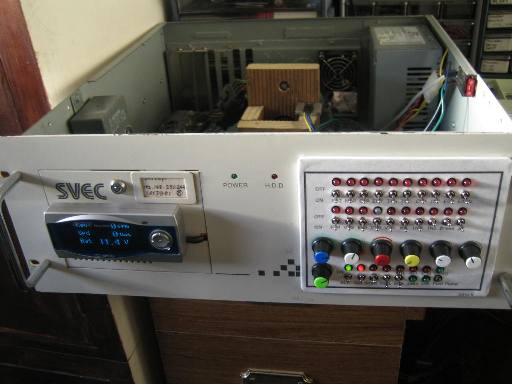 Everything is wired up as in the two bellow schematics "gsrwiring1.gif and gsrwiring2.gif"
- I am using variable resistors for the ECT, IAT, TPS, MAP, and EGR
- I have added 4x 5w resistors to simulate the injectors.
- I have wired up a EACV for the EACV
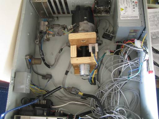
- I am using a distributor to achive the TDC, CYP, CKP from a OBDI car. Its driven by a 12v motor from an old cordless drill :). then the trigger from the cordless drill is conected to a varable resistor to be able to vary the speed of the motor which simulates the RPMs. The whole thing is built into a wooden jig that holds the dizzy and motor lined up together. I removed the camshaft drive from the dizzy and fit a 15 tooth tamiya gear from an RC car to the motor, then used fuel hose to link the two shafts. works great :)
- The ICM and coil has been wired up, 12v to the blk/yel wire from the main relay to prevent code 15 , but to control the coil Im switch the ground of the body of the dizzy.
- I made a circuit with a 555 timer IC to simulate the VSS, Ill add the schematic soon.
- EGR at the moment is just a varable resistor, Im working an a solution that will automaticly vary the trimpot with the pulses from the EGR sol output. It if works then Ill post the plans.
- using a real main relay for the main relay.
- I have added an actual VTEC solenoid for the VTEC solenoid. ( no better way to simulate the load of one.) its reasuring to hear the click when VTEC engages. also driving a bi colour LED on the front panel
- VTP is simply a relay driven from the VTS signal.
- I have added a knock sensor that I hit against the chassis of the thing to simulate knock. ( thanks to edgeauto for the sensor )
- there is 3x 3.7k 5w resistors ( all I could find on the day ) to simulate the Oxygen Sensor Heater.
- a LED is the MIL, used a 560R resistor to limmit the current to it then a 1k resistor across the LED to stop it from staying iluminated when it should not be.
- I have built an O2 simulator circuit from a 555 timer IC. I found the plans on the web.
- a LED that changes colours is used as the fuel pump. this simply lets me know the fuel pump is powered.
- Im going to add an ELD from a fues box I have to simulate that. or at least to figure out what it does and when it does it, to help build a simulator for it.
- added an APEXI RSM for the dash board so I can see the RPM's and Vehicle Speed and Battery Voltage. ( bit over the top but its well worth it )
Everything is wired up as in the two bellow schematics "gsrwiring1.gif and gsrwiring2.gif"
- I am using variable resistors for the ECT, IAT, TPS, MAP, and EGR
- I have added 4x 5w resistors to simulate the injectors.
- I have wired up a EACV for the EACV
- I am using a distributor to achive the TDC, CYP, CKP from a OBDI car. Its driven by a 12v motor from an old cordless drill :). then the trigger from the cordless drill is conected to a varable resistor to be able to vary the speed of the motor which simulates the RPMs. The whole thing is built into a wooden jig that holds the dizzy and motor lined up together. I removed the camshaft drive from the dizzy and fit a 15 tooth tamiya gear from an RC car to the motor, then used fuel hose to link the two shafts. works great :)
- The ICM and coil has been wired up, 12v to the blk/yel wire from the main relay to prevent code 15 , but to control the coil Im switch the ground of the body of the dizzy.
- I made a circuit with a 555 timer IC to simulate the VSS, Ill add the schematic soon.
- EGR at the moment is just a varable resistor, Im working an a solution that will automaticly vary the trimpot with the pulses from the EGR sol output. It if works then Ill post the plans.
- using a real main relay for the main relay.
- I have added an actual VTEC solenoid for the VTEC solenoid. ( no better way to simulate the load of one.) its reasuring to hear the click when VTEC engages. also driving a bi colour LED on the front panel
- VTP is simply a relay driven from the VTS signal.
- I have added a knock sensor that I hit against the chassis of the thing to simulate knock. ( thanks to edgeauto for the sensor )
- there is 3x 3.7k 5w resistors ( all I could find on the day ) to simulate the Oxygen Sensor Heater.
- a LED is the MIL, used a 560R resistor to limmit the current to it then a 1k resistor across the LED to stop it from staying iluminated when it should not be.
- I have built an O2 simulator circuit from a 555 timer IC. I found the plans on the web.
- a LED that changes colours is used as the fuel pump. this simply lets me know the fuel pump is powered.
- Im going to add an ELD from a fues box I have to simulate that. or at least to figure out what it does and when it does it, to help build a simulator for it.
- added an APEXI RSM for the dash board so I can see the RPM's and Vehicle Speed and Battery Voltage. ( bit over the top but its well worth it )
 The Control Pannel
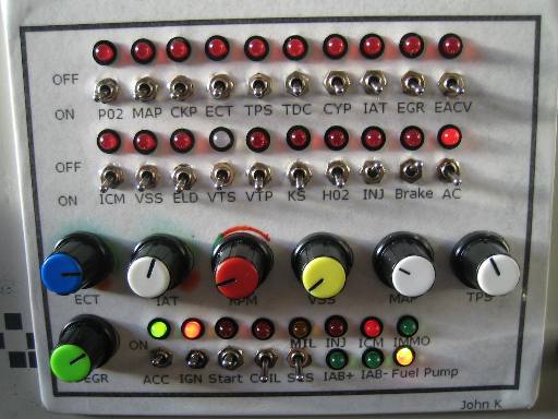 On the top two rows of switches I have added a switch and LED for each PGMFI component vital to PGMFI operation. the Switch will open circuit the sensor to the ECU to force MIL. This is done to help ECU repair and to confirm that a circuit has been disabled in code. example VTP, HO2, ELD, EACV ect, and ensure you dont get a code while operating the ECU. When the circuit is disabled the LED lights up red.
Some LED's also act as a indicator of what that circuit is doing. for example, the AC switch is wired to the AC switch input, but the LED is wired to the AC clutch relay output from the ECU.
A row of varable resistor pots is added for the ECT, IAT, RPM, VSS, TPS, MAP, EGR control. I simply turn these knobs to achive the desired signal level. You will get a MIL if you go out of range or simply move the ECT to fast. ( ECU gets worried when the ECT goes from 0deg to 90 deg in less than a second :).
On the bottom Row of switches and LED's are the basics to the simulator, like Acc then Ignition. I have wired up the start signal as in the schematic witch will also force the dizzy motor to run. If the dizzy motor pot is set to the low end the dizzy wont turn, however when you wind up the dizzy motor a little you can "Start the simulator" with the start switch, the dizzy motor will run Just as if the car was running. If I turn the RPM's to low ( 500 rpm ) the dizzy motor stalls :) just like an engine.
A LED to show injector and ICM pulse has been added to show whats happening their. Two LED's make up the IAB signal and its polarity. and the fuel pump LED that changes colour as the main relay is engaged. I added a Immo Led for later when I add an IMMO unit to the sim.
The pannel was drawn up in ms paint and printed on normal paper. Then used as a template on a peice of plastic from a sign and once the holes where all drilled then glued to the plastic with a clear coat of contact paper. then all the LEDs and Switched go in.
The ECU Interface
On the top two rows of switches I have added a switch and LED for each PGMFI component vital to PGMFI operation. the Switch will open circuit the sensor to the ECU to force MIL. This is done to help ECU repair and to confirm that a circuit has been disabled in code. example VTP, HO2, ELD, EACV ect, and ensure you dont get a code while operating the ECU. When the circuit is disabled the LED lights up red.
Some LED's also act as a indicator of what that circuit is doing. for example, the AC switch is wired to the AC switch input, but the LED is wired to the AC clutch relay output from the ECU.
A row of varable resistor pots is added for the ECT, IAT, RPM, VSS, TPS, MAP, EGR control. I simply turn these knobs to achive the desired signal level. You will get a MIL if you go out of range or simply move the ECT to fast. ( ECU gets worried when the ECT goes from 0deg to 90 deg in less than a second :).
On the bottom Row of switches and LED's are the basics to the simulator, like Acc then Ignition. I have wired up the start signal as in the schematic witch will also force the dizzy motor to run. If the dizzy motor pot is set to the low end the dizzy wont turn, however when you wind up the dizzy motor a little you can "Start the simulator" with the start switch, the dizzy motor will run Just as if the car was running. If I turn the RPM's to low ( 500 rpm ) the dizzy motor stalls :) just like an engine.
A LED to show injector and ICM pulse has been added to show whats happening their. Two LED's make up the IAB signal and its polarity. and the fuel pump LED that changes colour as the main relay is engaged. I added a Immo Led for later when I add an IMMO unit to the sim.
The pannel was drawn up in ms paint and printed on normal paper. Then used as a template on a peice of plastic from a sign and once the holes where all drilled then glued to the plastic with a clear coat of contact paper. then all the LEDs and Switched go in.
The ECU Interface
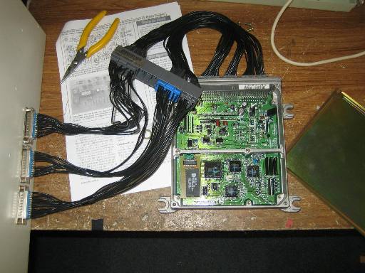 On the side of the case, I cut out 3 holes to suit D25 computer connectors. simply A B and D, just like on the OBDI ecu, and to keep things simple everyting is wired the same as the OBDI standard which helps when probing with a multimeter for sensor signal. I than have made Harneses to suit OBDIIa, OBDIIb OBDO, and when I get some conectors OBDI ( rather than using a harness.)
there are so many uses for this thing from fault finding faults on an ECU at the component level to testing code and PGMFI parts.
Im working on an electronic distriblutor simulator. but for now I like the noise of something widing up. ( adds the fun to reving up the sim ) :)
If anyone else has built such a thing as this here please post up some pics and Ideas.
discussion thread http://forum.pgmfi.org/viewtopic.php?p=83194#83194
cheers
John
b16a2 - 27 Jan 2007 from downunder
.
%META:FILEATTACHMENT{name="gsrwiring1.gif" attr="" comment="OBDI PGMFI schematic part 1" date="1169909722" path="W:\b16a2.kicks-ass.net\web\tech\gsrwiring1.gif" size="102200" user="b16a2" version="1.1"}%
%META:FILEATTACHMENT{name="gsrwiring2.gif" attr="" comment="OBDI PGMFI schematic part 2" date="1169909751" path="W:\b16a2.kicks-ass.net\web\tech\gsrwiring2.gif" size="71437" user="b16a2" version="1.1"}%
%META:FILEATTACHMENT{name="Engine_Sim001.jpg" attr="" comment="control panel of engine sim" date="1169909960" path="W:\b16a2.kicks-ass.net\web\tech\Engine_Sim001.jpg" size="39532" user="b16a2" version="1.1"}%
%META:FILEATTACHMENT{name="Engine_Sim009.jpg" attr="" comment="internals of engine sim" date="1169910006" path="W:\b16a2.kicks-ass.net\web\tech\Engine_Sim009.jpg" size="35521" user="b16a2" version="1.1"}%
%META:FILEATTACHMENT{name="Engine_Sim016.jpg" attr="" comment="front view of engine sim" date="1169910039" path="W:\b16a2.kicks-ass.net\web\tech\Engine_Sim016.jpg" size="29824" user="b16a2" version="1.1"}%
%META:FILEATTACHMENT{name="Engine_Sim018.jpg" attr="" comment="side view of engine sim" date="1169910092" path="W:\b16a2.kicks-ass.net\web\tech\Engine_Sim018.jpg" size="44419" user="b16a2" version="1.1"}%
On the side of the case, I cut out 3 holes to suit D25 computer connectors. simply A B and D, just like on the OBDI ecu, and to keep things simple everyting is wired the same as the OBDI standard which helps when probing with a multimeter for sensor signal. I than have made Harneses to suit OBDIIa, OBDIIb OBDO, and when I get some conectors OBDI ( rather than using a harness.)
there are so many uses for this thing from fault finding faults on an ECU at the component level to testing code and PGMFI parts.
Im working on an electronic distriblutor simulator. but for now I like the noise of something widing up. ( adds the fun to reving up the sim ) :)
If anyone else has built such a thing as this here please post up some pics and Ideas.
discussion thread http://forum.pgmfi.org/viewtopic.php?p=83194#83194
cheers
John
b16a2 - 27 Jan 2007 from downunder
.
%META:FILEATTACHMENT{name="gsrwiring1.gif" attr="" comment="OBDI PGMFI schematic part 1" date="1169909722" path="W:\b16a2.kicks-ass.net\web\tech\gsrwiring1.gif" size="102200" user="b16a2" version="1.1"}%
%META:FILEATTACHMENT{name="gsrwiring2.gif" attr="" comment="OBDI PGMFI schematic part 2" date="1169909751" path="W:\b16a2.kicks-ass.net\web\tech\gsrwiring2.gif" size="71437" user="b16a2" version="1.1"}%
%META:FILEATTACHMENT{name="Engine_Sim001.jpg" attr="" comment="control panel of engine sim" date="1169909960" path="W:\b16a2.kicks-ass.net\web\tech\Engine_Sim001.jpg" size="39532" user="b16a2" version="1.1"}%
%META:FILEATTACHMENT{name="Engine_Sim009.jpg" attr="" comment="internals of engine sim" date="1169910006" path="W:\b16a2.kicks-ass.net\web\tech\Engine_Sim009.jpg" size="35521" user="b16a2" version="1.1"}%
%META:FILEATTACHMENT{name="Engine_Sim016.jpg" attr="" comment="front view of engine sim" date="1169910039" path="W:\b16a2.kicks-ass.net\web\tech\Engine_Sim016.jpg" size="29824" user="b16a2" version="1.1"}%
%META:FILEATTACHMENT{name="Engine_Sim018.jpg" attr="" comment="side view of engine sim" date="1169910092" path="W:\b16a2.kicks-ass.net\web\tech\Engine_Sim018.jpg" size="44419" user="b16a2" version="1.1"}% |
|
Copyright © 2002-present by the contributing authors. All material on this collaboration platform is the property of the
contributing authors, and is covered by the Non-Commercial Share-Alike License unless explicitly stated otherwise. |
|