 |
 |
This page is a construction design for the Easy-RTP V1.0 board. This is the single sided design for a DS1230 style 28 pin DIP NVSRAM. You can find the eagle design files attached in a zipfile at the end of this thread. THIS ONLY WORKS WITH OBD1 ECU FOR NOW.
Brief Explanation
A quick explanation: the "optional components" are only required if you want 27C256 emulation. This is intended for those who do not have an EPROM programmer capable of natively programming their NVSRAM of choice. Most programmers "28C256" setting seem to do the trick nicely, FYI. (Tested with Willem by Calvin and the Batronix by gimpy... Gimpy sez you have to disable the blank check for it to work)
picture of board layout in eagle:
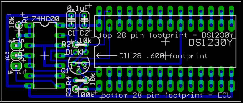
Parts list:
- DS1230Y or similar TI, ST, Simtek, ZMD, ... 32K 28 pin .600" DIP NVSRAM
- 74HC00 DIP package quad NAND gate
- 2x 0.1 uF ceramic caps (decoupling)
- 2x 10K resistors
- 2x 1x14 pin headers or similar contraption to make contact with ECU socket
Optional components: (required for 27C256 emulation)
- 1x 10K resistor
- 1x 100k resistor
- 1x generic NPN switching transistor (2N4401 or equivalent)
- 1x switching diode (1n4148, etc... not too picky.)
Construction:
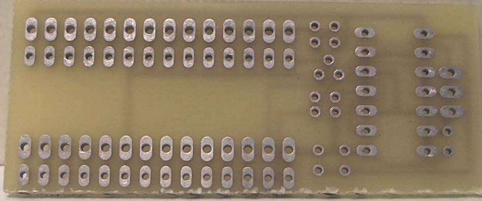
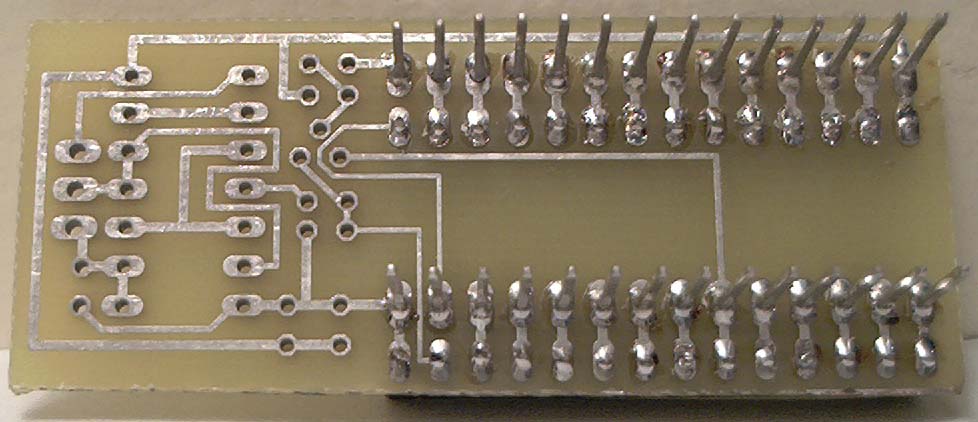
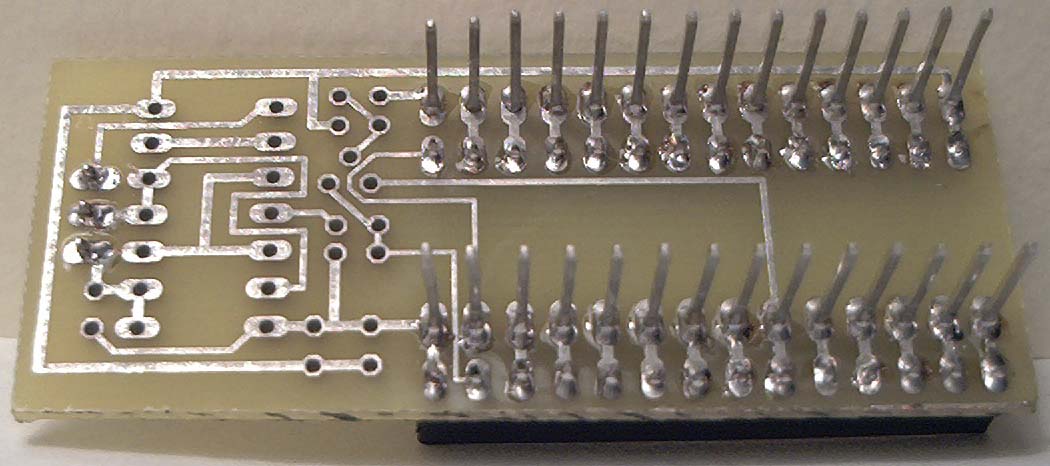
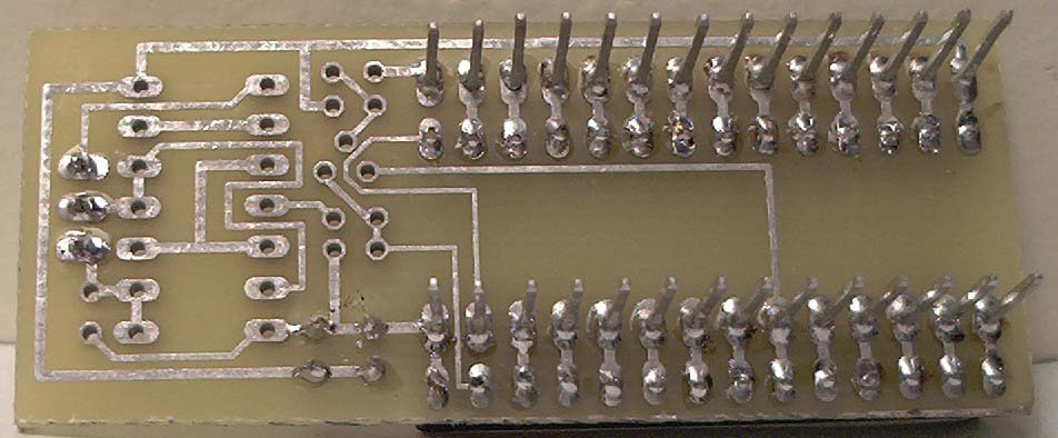
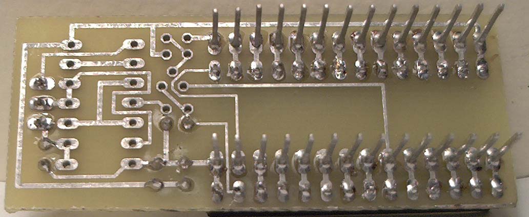
First off, orient your board with the traces facing up. (bottom up)
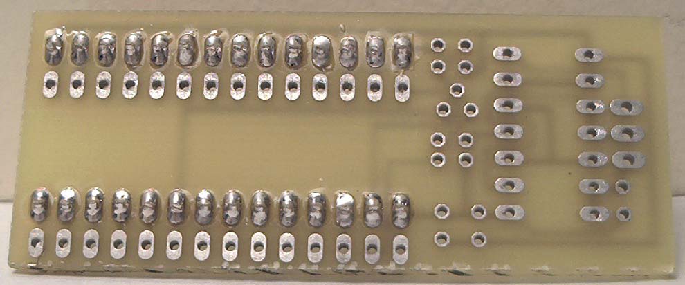
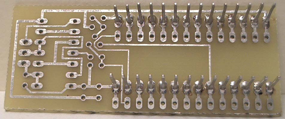
If you have the two 28 pin footprints facing right, the top set of holes (that are also larger diameter) are the ones to use for the ECU-board connectors. Solder in place the 2 - 1x14 pin headers (I'm ghetto, fuck off.) or whatever other contraption you are using to connect the board to the ECU in place and continue.
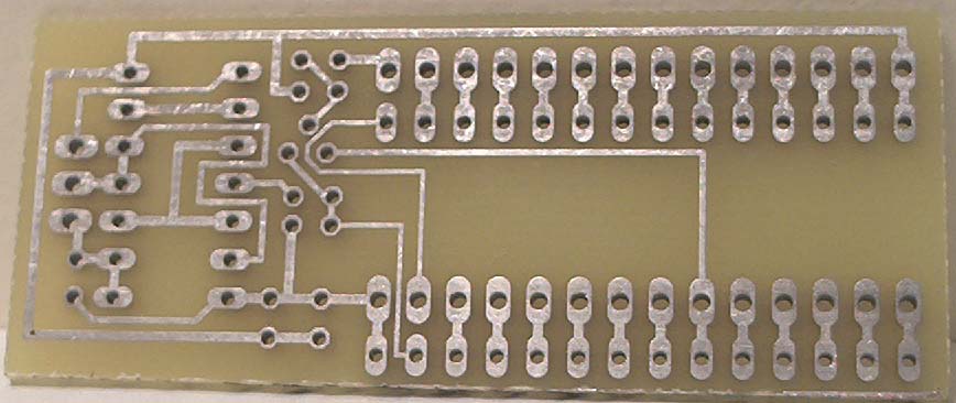
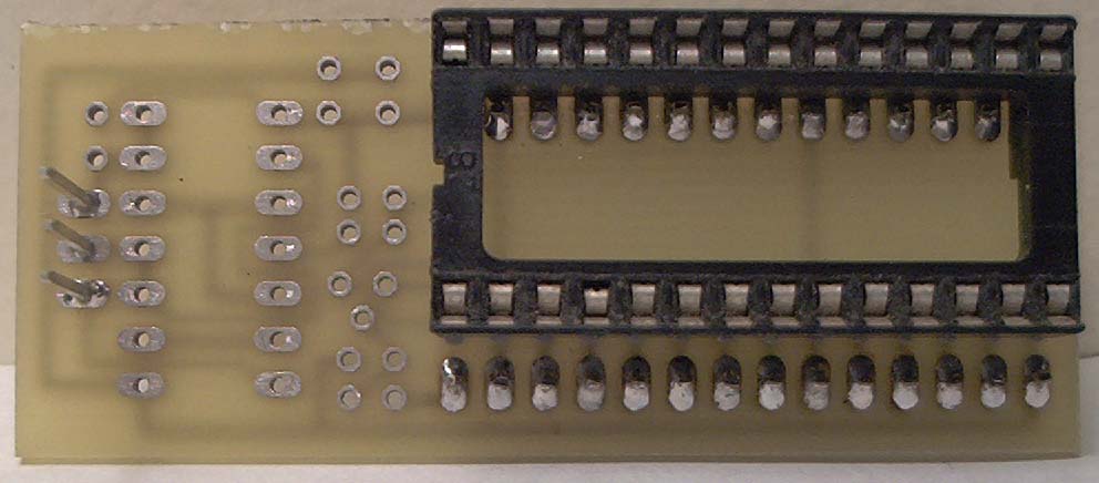
- Orient your board with the traces on the BOTTOM. Look at the top of the board (no traces). Orient your board so the 3 pin jumper connector faces left and the double 27C256 face right. This is the orientation in which all the following instructions will assume you are looking at the board.
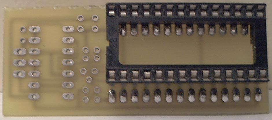
Next, solder in a 28 pin DIP socket for the NVSRAM in the top set of holes. The notch will face left.
Next, solder in a 3pin - pin header or 3 wires for J1.
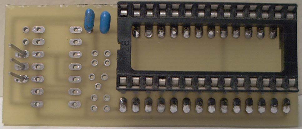
Next, solder the two caps C1+C2 in place.
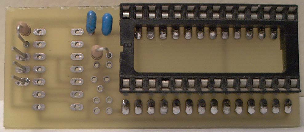
Next, solder in R1 (10k, to the left) and R2 (10K, center).
- Next decide whether you want/need 27C256 emulation.
IF YOU DON'T WANT 27C256 EMULATION:
- Solder in a wire link or 0-ohm resistor for D1
- Skip to FINAL STEPS.
IF YOU DO WANT 27C256 EMULATION:
- Solder in the switching diode for D1.
- Solder in the NPN switching transistor Q1.
- Solder in R3 (10k - top resistor)
- Solder in R4 (100k - bottom resistor)
- continue...
FINAL STEPS:
- Solder in the 74HC00 Latch
- Place the NVSRAM in the 28 pin DIP socket
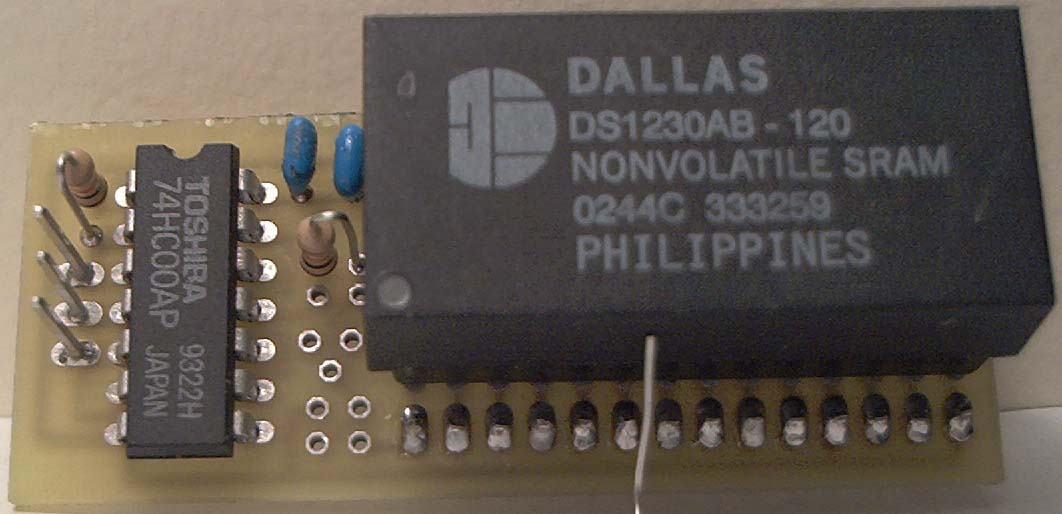
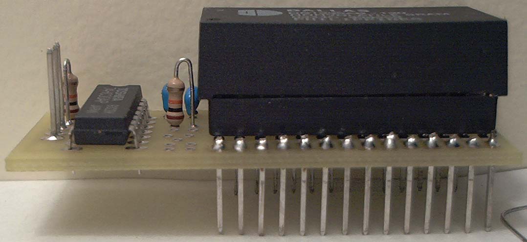
Final board
You can download the design or full size versions of any of the images:
Modification for OBD0 Application
Modification for OBD0 Application(while we make a version 2 of the board)
Okay then, here goes.
This is just one way of doing it. I´m sure someone can come up with a much cleaner way, but this was how I did it.
Needless to say, this is not my own design... l3st4rd is the evil genious here, not me Very Happy
You will need the following:
-PCB, resistors, sockets, pins, NVSRAM etc. as found in the excellent current kit (as sold by joshuavillasenor)
-1 pcs 74LS86N TTL chip
-1 pcs additional 10K ohm resistor
-Some thin insulated wire for making interconnections on the board
How-to build/modify the board itself:
-Cut the connections marked RED in the first picture
-Assemble the RTP as per the excellent instructions in Wi Ki
-Cut or break off all pins except 4,5,6,7 and 14 from the 74LS86N (see picture 3)
-Solder the 74LS86N on top of the 74LS00 (piggy backed!) - but ONLY pins 4, 7 and 14.
-Bend the remaining pins 5 and 6 upwards so you can solder wires to them.
-Using thin wire, make the connections as indicated in the first and second picture. The chip shown is the 74LS86N. This assumes of course that it is soldered on top of the 74LS00 as shown in the Wi Ki directions.
-The resistor shown(or rather, crudely drawn!) in the second picture is 10Kohm
Shielding (optional):
One of the connections made is pin 2 on the 3-pin header. If you make this connection, you will have a nice ground signal for connecting to a shield on a shielded cable.
The A15 signal for which pin 2 was originally intended is now connected elsewhere.
Connecting to the ECU:
You will need to isolate pin 16 from the ECU. Sorry no pictures, as I don´t have my ECU with me at the moment.
-One connection must be cut going to the 24-pin SRAM on the top of the board.
-Another must be cut on the bottom of the board.
-These two points must be re-connected so that only the ECU pin is "disconnected" and the rest of the circuit is complete.
-Connect one RTP wire to pin 16 on the ECU (connect this to the INPUT on RTP)
-Connect one RTP wire to pin 21 on the 24-pin SRAM (M5128)
That´s all I have time for now - hope it helps.
/Bindegal


| Attachment?: | Modify: | Size: | Date: | Who: | Comment: |
|---|
 easyrtpv1-eagle.zip easyrtpv1-eagle.zip | mod | 34574 | 21 Feb 2004 - 00:24 | blundar | The design in eagle format |
 IM000495.JPG IM000495.JPG | mod | 54179 | 22 Apr 2004 - 17:54 | blundar | bottom of rtp board |
| IM000496.JPG | mod | 48789 | 22 Apr 2004 - 17:54 | blundar | top of rtp board |
| IM000497.JPG | mod | 60302 | 22 Apr 2004 - 18:07 | blundar | board with pin headers - top |
| IM000498.JPG | mod | 68144 | 22 Apr 2004 - 18:08 | blundar | board with pin headers - bottom |
| IM000499.JPG | mod | 48925 | 22 Apr 2004 - 18:09 | blundar | Image of board front with socket |
| IM000500.JPG | mod | 67878 | 22 Apr 2004 - 18:10 | blundar | Image of board back with socket |
| IM000501.JPG | mod | 56798 | 22 Apr 2004 - 18:10 | blundar | Image of board front with 3 pin header |
| IM000502.JPG | mod | 78703 | 22 Apr 2004 - 18:10 | blundar | Image of board back with 3 pin header |
| IM000503.JPG | mod | 56249 | 22 Apr 2004 - 18:11 | blundar | Image of board front with Capacitors |
| IM000504.JPG | mod | 70396 | 22 Apr 2004 - 18:11 | blundar | Image of board back with Capacitors |
| IM000505.JPG | mod | 56663 | 22 Apr 2004 - 18:12 | blundar | Image of board front with resistors |
| IM000506.JPG | mod | 74566 | 22 Apr 2004 - 18:12 | blundar | Image of board back with resistors |
| IM000507.JPG | mod | 61984 | 22 Apr 2004 - 18:12 | blundar | Image of board front with 74HC00 |
| IM000508.JPG | mod | 75290 | 22 Apr 2004 - 18:13 | blundar | Image of board back with 74HC00 |
| IM000509.JPG | mod | 64788 | 22 Apr 2004 - 18:13 | blundar | Image of board front with DS1230Y |
| IM000510.JPG | mod | 57468 | 22 Apr 2004 - 18:14 | blundar | Image of board with DS1230Y |
 rtp_EasyRtpV10-v1.pdf rtp_EasyRtpV10-v1.pdf | mod | 482308 | 15 Mar 2004 - 02:35 | The_DoC | This Page in PDF form (no install instructions) |
| doc_RTP_OBD1.jpg | mod | 62057 | 12 Apr 2004 - 21:29 | tungsten2k | doc's original design installed in ECU |
| doc_RTP_OBD1_Cut_here.jpg | mod | 70898 | 12 Apr 2004 - 21:30 | tungsten2k | doc's original info on where to cut WE line in ECU |
 boardlayout.png boardlayout.png | mod | 33830 | 22 Apr 2004 - 18:05 | blundar | picture of board layout in eagle |
|
Copyright © 2002-present by the contributing authors. All material on this collaboration platform is the property of the
contributing authors, and is covered by the Non-Commercial Share-Alike License unless explicitly stated otherwise. |
|