 |
 |
|
|
| Changed: |
<
< |
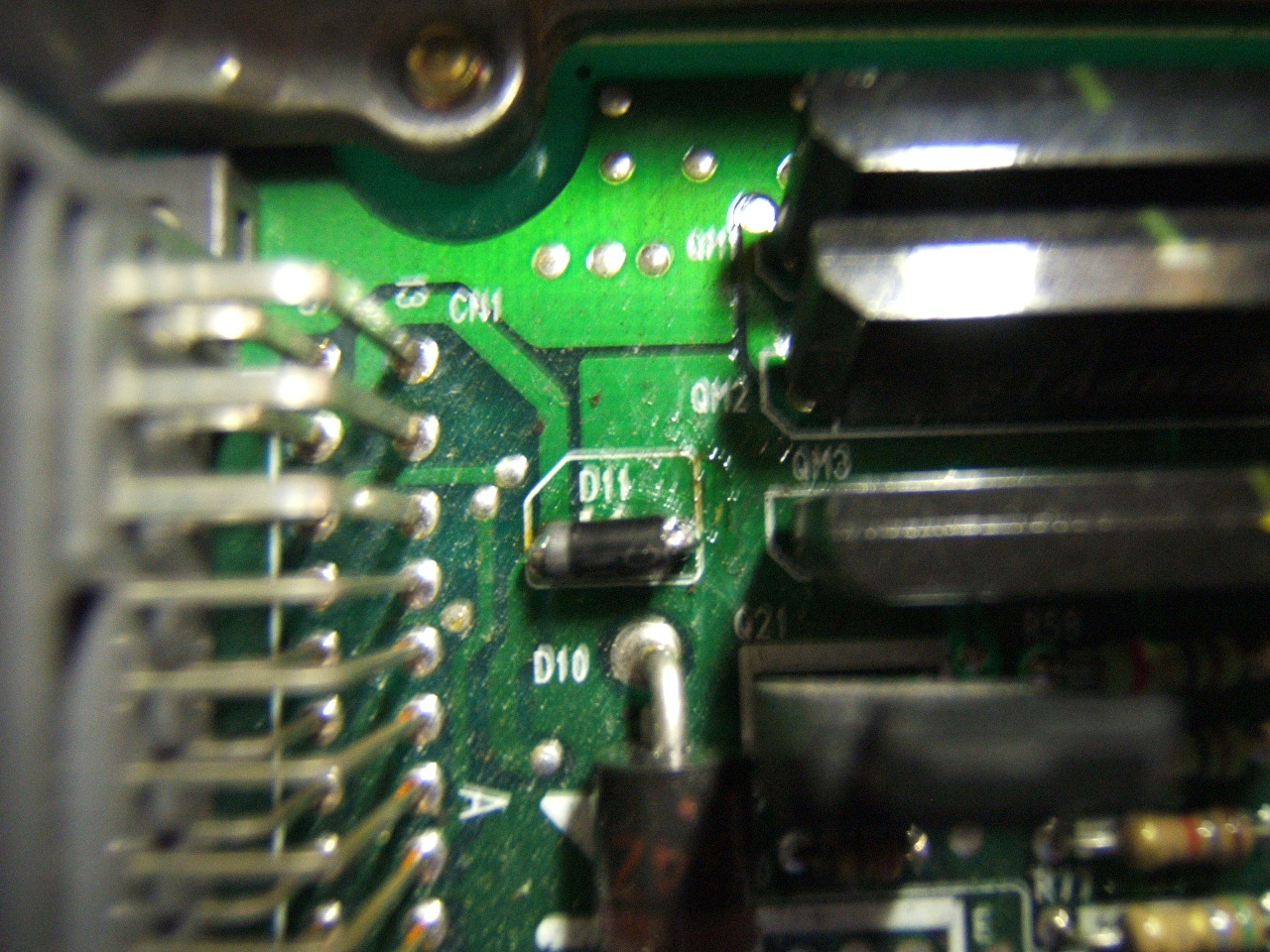
- D11 Diode - upper left in the case:
| >
> |
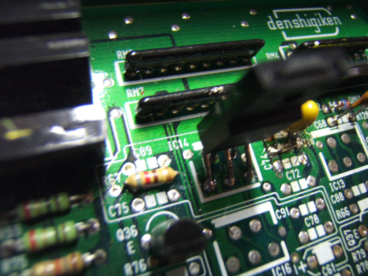
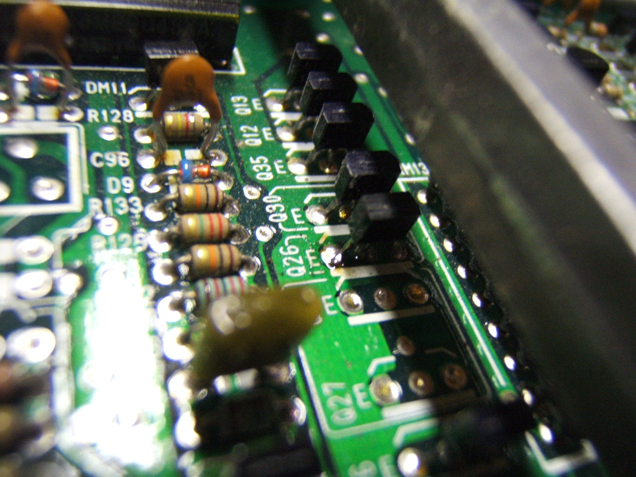
- IC14 5151S (thanks to Xenocron) AND R67 Resistor:
|
| Changed: |
<
< |
- IC14 5151S (thanks to Xenocron):
| >
> |
- D11 Diode - upper left in the case:
|
| Added: |
>
> |
|
| Deleted: |
<
< |
%META:FILEATTACHMENT{name="DSCF1763.JPG" attr="" comment="IC14 5151S (thanks to Xenocron) AND R67 Resistor" date="1173836847" path="DSCF1763.JPG" size="468390" user="defensio" version="1.1"}%
|
| Added: |
>
> |
%META:FILEATTACHMENT{name="DSCF1763.JPG" attr="" comment="IC14 5151S (thanks to Xenocron) AND R67 Resistor" date="1173849000" path="DSCF1763.JPG" size="468390" user="defensio" version="1.1"}% |
|
|
| Changed: |
<
< |
- RM11: weird voltage divider (this is KEY but can be replaced. Click link for more info)
| >
> |
- RM11: weird voltage divider (this is KEY but can be replaced. Click link for more info)this could be replace by a 10k 8pin resistor module work really well
|
| Changed: |
<
< |
- R67: 820 Ohm, 1/8w 5% resistor (1k work fine says Deluded)
| >
> |
- R66: 820 Ohm, 1/8w 5% resistor (1k work fine says Deluded)
|
| Added: |
>
> |
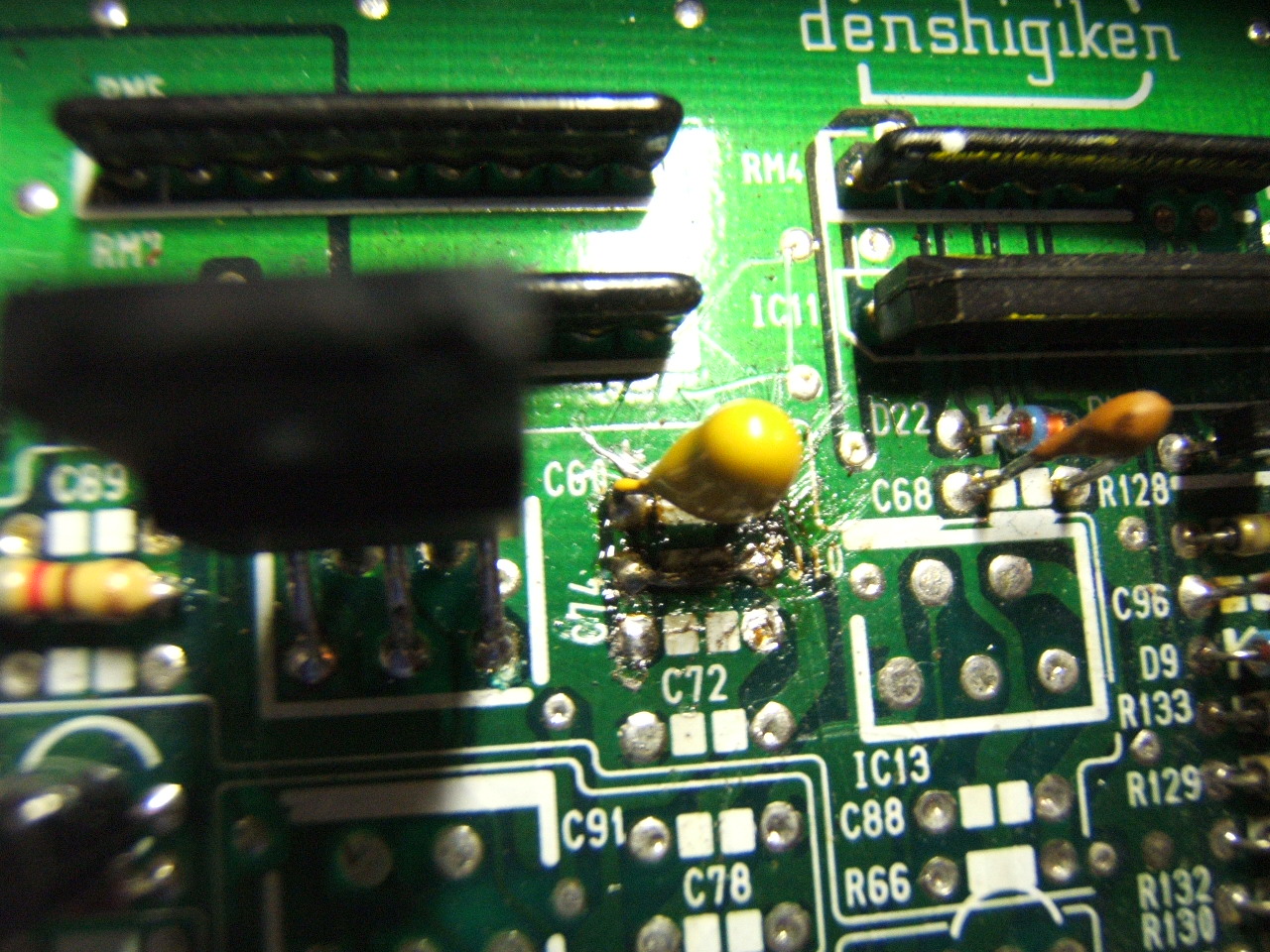
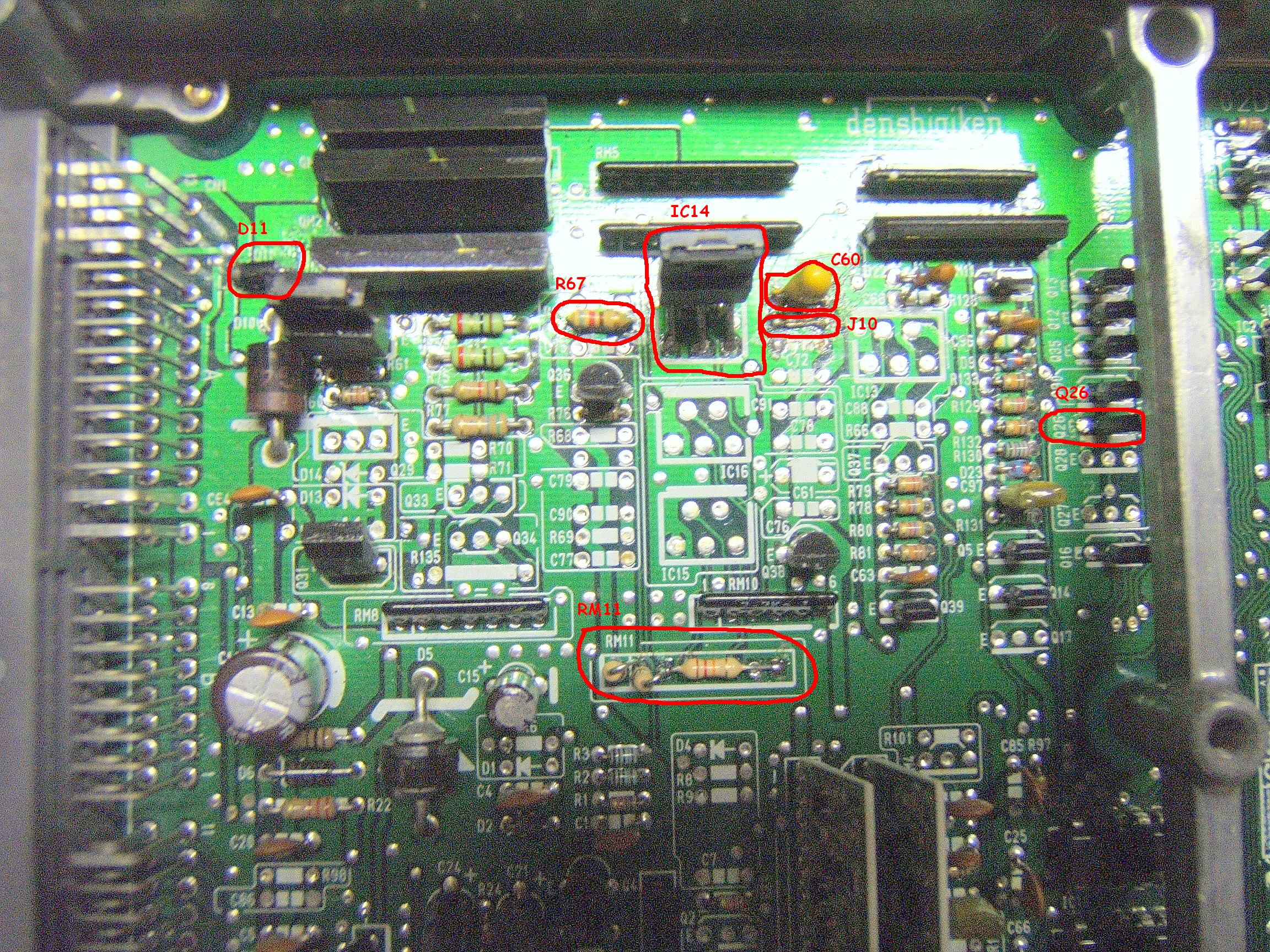
- C60 and J10 - Top left of the case:
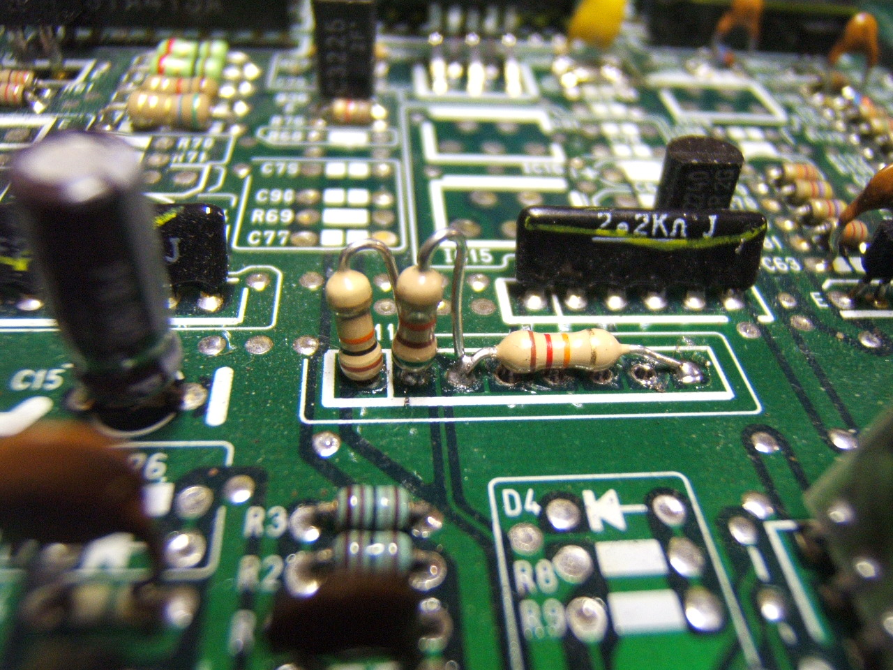
- Resistor setup in RM11:
- Q26 NPN Transistor:
- D11 Diode - upper left in the case:
- IC14 5151S (thanks to Xenocron):
- overview with comment:
|
| Added: |
>
> |
%META:FILEATTACHMENT{name="DSCF1764.JPG" attr="" comment="C60 and J10 - Top left of the case" date="1173836480" path="DSCF1764.JPG" size="466150" user="defensio" version="1.1"}%
%META:FILEATTACHMENT{name="DSCF1766.JPG" attr="" comment="Resistor setup in RM11" date="1173836607" path="DSCF1766.JPG" size="467869" user="defensio" version="1.1"}%
%META:FILEATTACHMENT{name="DSCF1765.JPG" attr="" comment="Q26 NPN Transistor" date="1173836690" path="DSCF1765.JPG" size="480298" user="defensio" version="1.1"}%
%META:FILEATTACHMENT{name="DSCF1762.JPG" attr="" comment="D11 Diode - upper left in the case" date="1173836758" path="DSCF1762.JPG" size="475259" user="defensio" version="1.1"}%
%META:FILEATTACHMENT{name="DSCF1763.JPG" attr="" comment="IC14 5151S (thanks to Xenocron) AND R67 Resistor" date="1173836847" path="DSCF1763.JPG" size="468390" user="defensio" version="1.1"}%
%META:FILEATTACHMENT{name="DSCF1759_modified.JPG" attr="" comment="overview with comment" date="1173839293" path="DSCF1759_modified.JPG" size="1179213" user="defensio" version="1.1"}% |
|
|
| Changed: |
<
< |
| >
> |
|
| Added: |
>
> |
#IC13note : IC13 is entirely superfluous. You can 100% safely remove it and install J10 to bypass it. IC13+IC14 are run in series, so if you have both installed you actually increase the probability of failure becuase you have 5x5x to possibly fail, not one. |
|
|
| Added: |
>
> |
%META:TOPICINFO{author="tungsten2k" date="1077704866" format="1.0" version="1.1"}%
To convert a "1720" board from non-vtec to vtec add the following parts:
Required:
- Q26: C2785 (*note: I used a C144 and it worked fine - NPN switching transistor)
- C60: 1uF 35v tantalum (marked "1 ... 35" and blue w/+ mark)
- IC14: 515 X High Side Switch
- J10: jumper wire
- R67: 820 Ohm, 1/8w 5% resistor (1k work fine says Deluded)
- RM11: weird voltage divider (this is KEY but can be replaced. Click link for more info)
- D11: Clamping Diode
Optional:
- C75,C89,C72,C74,C88: 22pF ceramic (marked "22")
- IC13: 515 X High Side Switch1?
- R67: 820 Ohm, 1/8w 5% resistor (1k work fine says Deluded)
This is Honda's first OBD1 Civic/Integra vtec design. It is more complicated than it needs to be - the optional components are overkill. |
|
Copyright © 2002-present by the contributing authors. All material on this collaboration platform is the property of the
contributing authors, and is covered by the Non-Commercial Share-Alike License unless explicitly stated otherwise. |
|