 |
 |
To convert a "1720" board from non-vtec to vtec add the following parts:
Required:
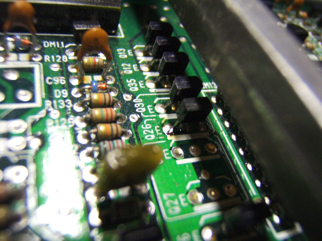
- Q26: C2785 (*note: I used a C144 and it worked fine - NPN switching transistor)
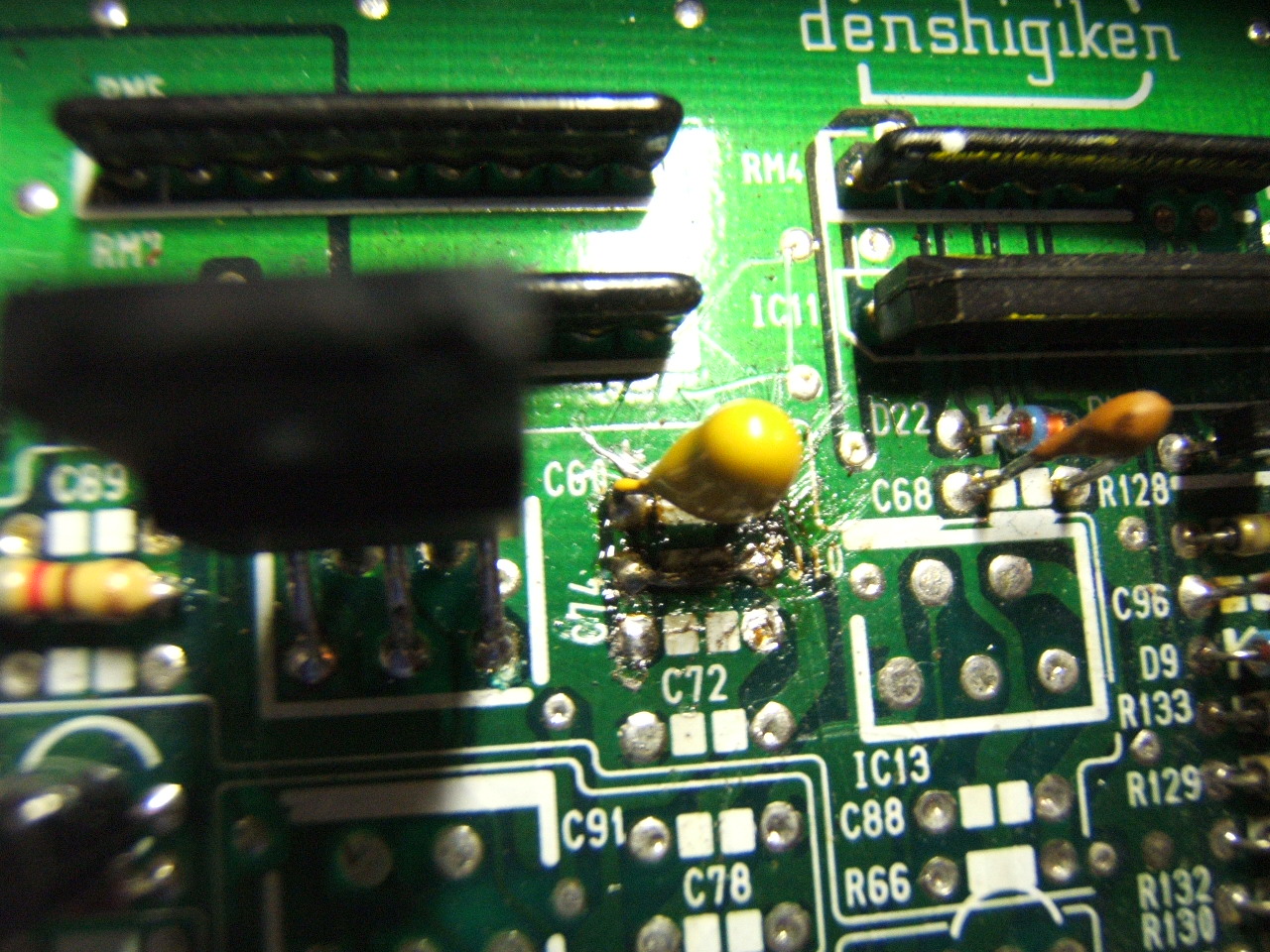
- C60: 1uF 35v tantalum (marked "1 ... 35" and blue w/+ mark)
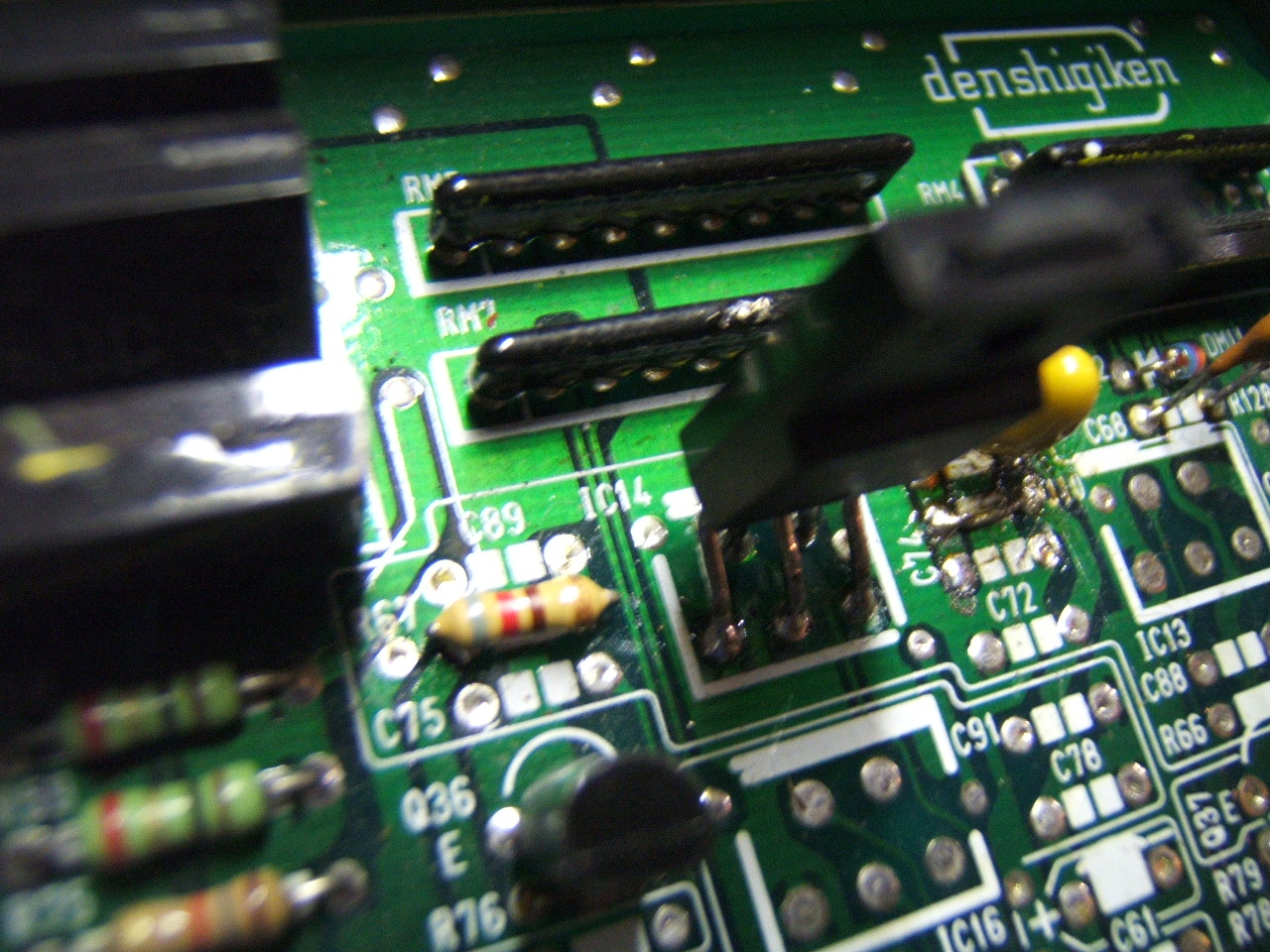
- IC14: 515 X High Side Switch
- J10: jumper wire
- R67: 820 Ohm, 1/8w 5% resistor (1k work fine says Deluded)
- RM11: weird voltage divider (this is KEY but can be replaced. Click link for more info)this could be replace by a 10k 8pin resistor module work really well
- D11: Clamping Diode
Optional:
- C75,C89,C72,C74,C88: 22pF ceramic (marked "22")
- IC13: 515 X High Side Switch (note)
- R66: 820 Ohm, 1/8w 5% resistor (1k work fine says Deluded)
This is Honda's first OBD1 Civic/Integra vtec design. It is more complicated than it needs to be - the optional components are overkill.
#IC13note : IC13 is entirely superfluous. You can 100% safely remove it and install J10 to bypass it. IC13+IC14 are run in series, so if you have both installed you actually increase the probability of failure becuase you have 5x5x to possibly fail, not one.
Find the Parts For ECUs Here
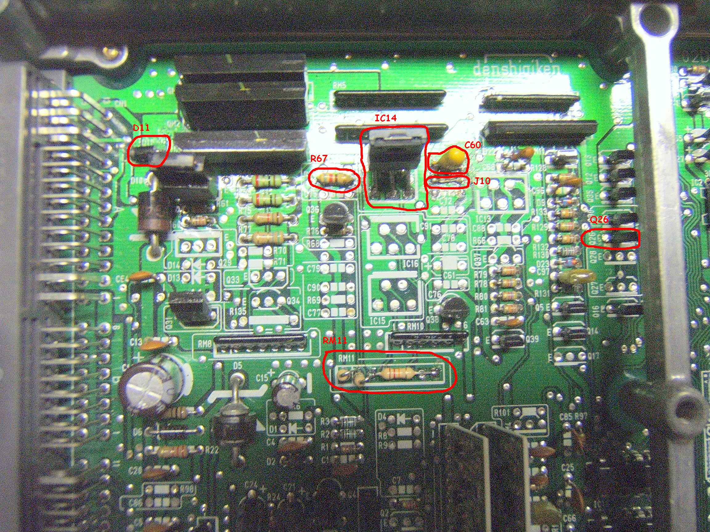
- C60 and J10 - Top left of the case:
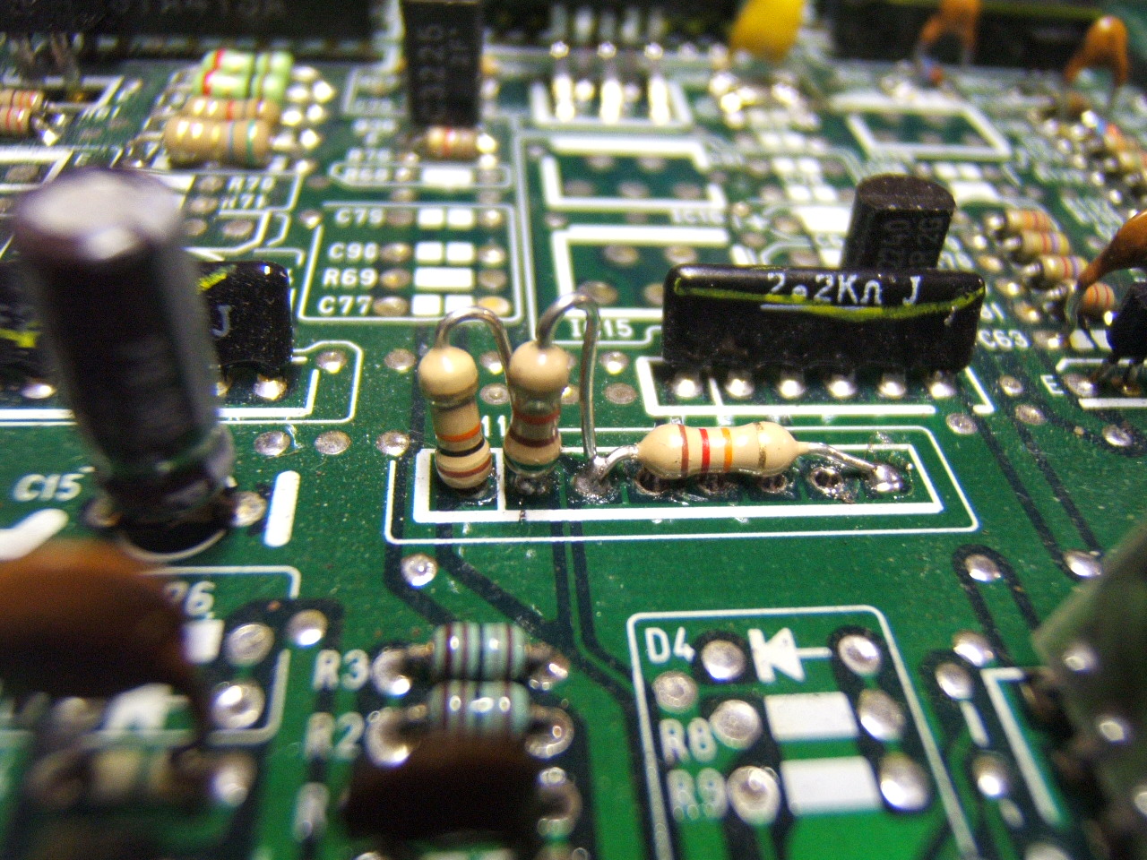
- Resistor setup in RM11:
- Q26 NPN Transistor:
- IC14 5151S (thanks to Xenocron) AND R67 Resistor:
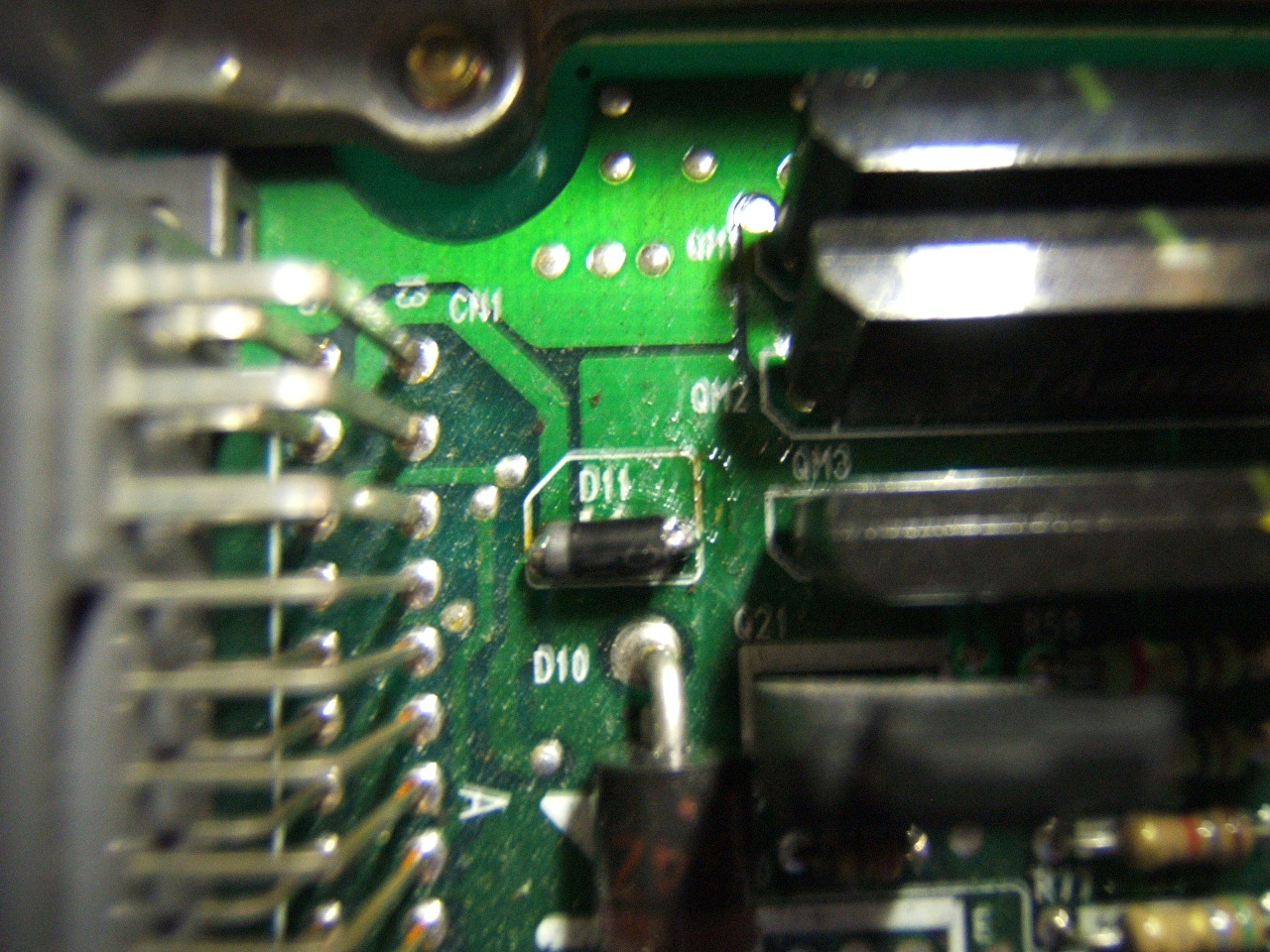
- D11 Diode - upper left in the case:
- overview with comment:
| Attachment?: | Modify: | Size: | Date: | Who: | Comment: |
|---|
 DSCF1764.JPG DSCF1764.JPG | mod | 466150 | 14 Mar 2007 - 01:41 | defensio | C60 and J10 - Top left of the case |
| DSCF1766.JPG | mod | 467869 | 14 Mar 2007 - 01:43 | defensio | Resistor setup in RM11 |
| DSCF1765.JPG | mod | 480298 | 14 Mar 2007 - 01:44 | defensio | Q26 NPN Transistor |
| DSCF1762.JPG | mod | 475259 | 14 Mar 2007 - 01:45 | defensio | D11 Diode - upper left in the case |
| DSCF1759_modified.JPG | mod | 1179213 | 14 Mar 2007 - 02:28 | defensio | overview with comment |
| DSCF1763.JPG | mod | 468390 | 14 Mar 2007 - 05:10 | defensio | IC14 5151S (thanks to Xenocron) AND R67 Resistor |
|
Copyright © 2002-present by the contributing authors. All material on this collaboration platform is the property of the
contributing authors, and is covered by the Non-Commercial Share-Alike License unless explicitly stated otherwise. |
|