 |
 |
|
|
| Added: |
>
> |
|
| Added: |
>
> |
%META:FILEATTACHMENT{name="USDMc42.JPG" attr="h" comment="USDM C42 Installed" date="1136176129" path="C:\Documents and Settings\mwolson\My Documents\Chron\HondaProject\EGTsensor\USDMc42.JPG" size="59898" user="markolson" version="1.1"}% |
|
|
| Added: |
>
> |
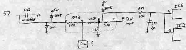
- josevar700's D12 ADC Schematics:
|
| Changed: |
<
< |
Bottom line is, you can put any 0 to 5V signal on a USDM P30 D12 pin, and log it by reading RAM location 0067h. That RAM location contains a byte that gives you the input voltage in 0.02V increments from 0V at 00h to 5V at 0FFh. Keep in mind that there is about a 1% drop in voltage from pin D12 to Pin 57 on the 66207 chip (AI3 analog input port), although that is probably negligent. If you want to get really accurate, you can also read RAM location 0066h to get the least significant two bits of the 10 bit A/D converter data, but that seems like overkill for EGT logging. Note that in the USDM P30, the AI5 analog input pin is grounded.
| >
> |
Bottom line is, you can put any 0 to 5V signal on a USDM P30 D12 pin, and log it by reading RAM location 0067h. That RAM location contains a byte that gives you the input voltage in 0.02V increments from 0V at 00h to 5V at 0FFh. Keep in mind that there is about a 1% drop in voltage from pin D12 to Pin 57 on the 66207 chip (AI3 analog input port), although that is probably negligent. If you want to get really accurate, you can also read RAM location 0066h to get the least significant two bits of the 10 bit A/D converter data, but that seems like overkill for EGT logging.
C42 is unstuffed in a stock USDM ECU, so it is a really good idea to put a 1uF 35V tantalum cap in C42. This provides a nice filter to smooth the ADC analog input. Make sure you install the cap with the plus side the same as all of the other caps in that row, away from the 66207.
Note that in the USDM P30, the AI5 analog input pin is grounded.
|
| Changed: |
<
< |
Another application for this input could be for a kill switch input. A clever person could use this feature to make a plugin for the ECU software to read a kill switch with a pullup resistor to disable the ECU if the switch is set to disable the ECU or enable the ECU if the switch is the other way. Of course, that would make it so you couldn't log EGTs or anything else, but not everyone is into logging. There are probably a lot of other applications that D12 could be used for. We just need clever programmers.
-- markolson - 20 Nov 2005
| >
> |
You could use this input as a 0-5V input for a wideband O2 data, leaving the stock O2 sensor input for the narrow band O2 data. Another application for this input could be for a kill switch input. A clever person could use this feature to make a plugin for the ECU software to read a kill switch with a pullup resistor to disable the ECU if the switch is set to disable the ECU or enable the ECU if the switch is the other way. Of course, that would make it so you couldn't log EGTs or anything else, but not everyone is into logging. There are probably a lot of other applications that D12 could be used for. We just need clever programmers.
|
| Added: |
>
> |
-- markolson - 20 Nov 2005, Edited -- markolson - 02 Jan 2006
|
| Added: |
>
> |
%META:FILEATTACHMENT{name="adc.jpg" attr="h" comment="josecar700's ADC schematics" date="1136170944" path="C:\Documents and Settings\mwolson\My Documents\Chron\HondaProject\P30Schematics\adc.jpg" size="134133" user="markolson" version="1.1"}%
%META:FILEATTACHMENT{name="USDMD12adc.jpg" attr="h" comment="josevar700's D12 ADC Schematics" date="1136171536" path="C:\Documents and Settings\mwolson\My Documents\Chron\HondaProject\P30Schematics\USDMD12adc.jpg" size="5920" user="markolson" version="1.1"}% |
|
|
| Changed: |
<
< |
Fortunately, there is a spare undocumented analog input on the USDM P30 ECU on connector D, pin 12. JDM P30 ECUs also have an undocumented input on that connector, but it has some uninstalled components in that circuit and it goes to a different Analog Input port on the 66207 chip. Other USDM OBD1 ECUs should have the same D12 circuit as the USDM P30, and other JDM OBD1 ECUs should have the same D12 circuit as the JDM P30, but I will let others add confirmation here later.
| >
> |
Fortunately, there is a spare undocumented analog input on the USDM P30 ECU on connector D, pin 12. JDM P30 ECUs also have an undocumented input on that connector, but it has some uninstalled components in that circuit and it goes to a different Analog Input port on the 66207 chip. Other USDM OBD1 ECUs should have the same D12 circuit as the USDM P30, and other JDM OBD1 ECUs should have the same D12 circuit as the JDM P30, but I will let others add confirmation here later. It looks like the USDM P28 has the same D12 circcuitry as the USDM P30.
|
| Changed: |
<
< |
That thread also has the schematic for the D12 circuit in the JDM P30. I have no idea what the values of the uninstalled components should be for the input to work in the same way as the USDM D12 circuit works. I'll let others add that here. Also, the JDM D12 circuit goes to the 66207 chip pin 63 which is its AI5 analog input port. Note that in the JDM P30, the AI3 analog input port is grounded.
| >
> |
That thread also has the schematic for the D12 circuit in the JDM P30. I have figured out how to modify that circuit to enable D12 logging with a JDM P30. Also, the JDM D12 circuit goes to the 66207 chip pin 63 which is its AI5 analog input port. Note that in the JDM P30, the AI3 analog input port is grounded.
Here is a deeper description of the Japanese Domestic Market P30 D12 Modification with schematics and a high resolution photo of the JDM P30 modifications.
|
| Changed: |
<
< |
-- markolson - 24 Oct 2005
| >
> |
-- markolson - 20 Nov 2005
%META:FILEATTACHMENT{name="JDMp30D12ModPin63.JPG" attr="h" comment="JDM P30 D12 mod to enable analog input logging" date="1132472273" path="C:\Documents and Settings\mwolson\My Documents\Chron\HondaProject\EGTsensor\JDMp30D12ModPin63.JPG" size="159250" user="markolson" version="1.1"}% |
|
|
| Added: |
>
> |
%META:TOPICINFO{author="markolson" date="1130139129" format="1.0" version="1.1"}%
%META:TOPICPARENT{name="DataLogging"}%
Wouldn't it be nice to use your ECU to log data from and aftermarket sensor such as data from an EGT sensor? If you could, it would be relatively easy to use the O2 sensor data to tune your AF mixture and the EGT sensor data to tune your ignition timing, so you can really dial things in.
Fortunately, there is a spare undocumented analog input on the USDM P30 ECU on connector D, pin 12. JDM P30 ECUs also have an undocumented input on that connector, but it has some uninstalled components in that circuit and it goes to a different Analog Input port on the 66207 chip. Other USDM OBD1 ECUs should have the same D12 circuit as the USDM P30, and other JDM OBD1 ECUs should have the same D12 circuit as the JDM P30, but I will let others add confirmation here later.
Thanks to josecar700 we have the schematics of the USDM P30 analog input section here: http://forum.pgmfi.org/viewtopic.php?t=4082
Bottom line is, you can put any 0 to 5V signal on a USDM P30 D12 pin, and log it by reading RAM location 0067h. That RAM location contains a byte that gives you the input voltage in 0.02V increments from 0V at 00h to 5V at 0FFh. Keep in mind that there is about a 1% drop in voltage from pin D12 to Pin 57 on the 66207 chip (AI3 analog input port), although that is probably negligent. If you want to get really accurate, you can also read RAM location 0066h to get the least significant two bits of the 10 bit A/D converter data, but that seems like overkill for EGT logging. Note that in the USDM P30, the AI5 analog input pin is grounded.
You can go here to read the entire thread on how this was figured out and how it works: http://forum.pgmfi.org/viewtopic.php?p=34134#34134
That thread also has the schematic for the D12 circuit in the JDM P30. I have no idea what the values of the uninstalled components should be for the input to work in the same way as the USDM D12 circuit works. I'll let others add that here. Also, the JDM D12 circuit goes to the 66207 chip pin 63 which is its AI5 analog input port. Note that in the JDM P30, the AI3 analog input port is grounded.
Another application for this input could be for a kill switch input. A clever person could use this feature to make a plugin for the ECU software to read a kill switch with a pullup resistor to disable the ECU if the switch is set to disable the ECU or enable the ECU if the switch is the other way. Of course, that would make it so you couldn't log EGTs or anything else, but not everyone is into logging. There are probably a lot of other applications that D12 could be used for. We just need clever programmers.
-- markolson - 24 Oct 2005 |
|
Copyright © 2002-present by the contributing authors. All material on this collaboration platform is the property of the
contributing authors, and is covered by the Non-Commercial Share-Alike License unless explicitly stated otherwise. |
|